Ad Widget

Collapse

Announcement

Collapse
No announcement yet.

Fender style neg bias adjust vs balance

Collapse
X
 
  • Filter
  • Time
  • Show
Clear All
new posts

  • Fender style neg bias adjust vs balance

    Hi,
    I'm trying to focus some study on the differences between the Bias Adjustment and the Bias Balance circuits common to Fender Blackface and Silverface guitar amps.

    I made some drawings to help clarify my thoughts. I think they respresent in a genericized way the basic difference between the Adjust and Balance circuits.

    I am writing to ask if anyone can critique/check/proof/comment the drawings, especially if I made a mistake.
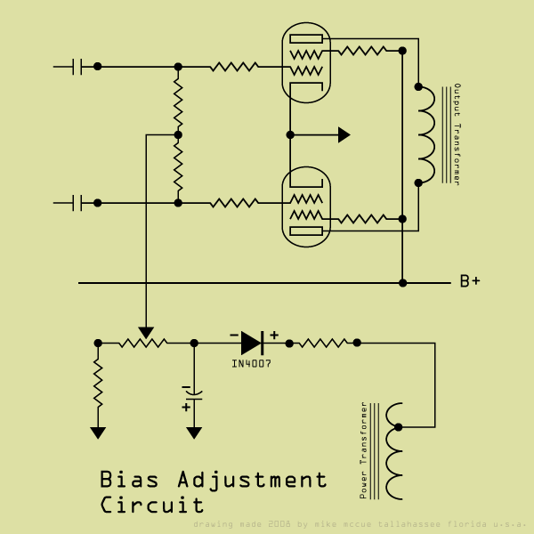
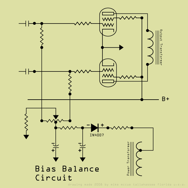


    Is the Bias Balance pot a specialty item? The forth solder tab on the back seems unfamiliar.

    thanks for taking a look,
    mike

  • #2
    anyone?

    please.

    best regards,
    mike

    Comment


    • #3
      Tapped pots are almost always a special order with setup and tooling charges. You might find some at a surplus store but they are not an off the shelf stocked part. One common use for tapped pots was the "loudness" control found on low cost audio equipment where an RC network is connected to the tap via a switch to give a bass boost at low volume. Fender used a 350K pot with a 70K tap on early 60's amps as a treble control. Weber VST has some made in China for people making replicas of those amps.
      WARNING! Musical Instrument amplifiers contain lethal voltages and can retain them even when unplugged. Refer service to qualified personnel.
      REMEMBER: Everybody knows that smokin' ain't allowed in school !

      Comment


      • #4
        Your drawings look fine and easy to follow.

        I have a couple of comments that apply
        - the bias adjust circuit lets you set the overall bias to your preference, but works best with matched tubes.
        - the bias balance lets you get away with unmatched tubes, but the overall bias level is set by the manufacturer

        The ideal setup is an individual bias pot per output tube, but this requires a separate PI coupling cap per output, a separate 1-ohm cathode resistor per tube (1mV/mA), and ideally, terminals that let you measure each tube's bias from outside the chassis. Each bias pot, then needs to be adjustable from outside as well, but not bumpable.

        This still isn't "perfect", but is safe - no terminals at B+ or anything.

        Hope this helps!

        Comment


        • #5
          Thanks to both for taking a look and answering questions.

          One last question:

          Now that I know that I don't really know much about tapped potentiometers I wonder if I used a correct representation schematically. Is there a more common symbol? Or did I fake it ok?

          thanks again,
          mike

          Comment


          • #6
            Originally posted by mike_mccue View Post
            Thanks to both for taking a look and answering questions.

            One last question:

            Now that I know that I don't really know much about tapped potentiometers I wonder if I used a correct representation schematically. Is there a more common symbol? Or did I fake it ok?

            thanks again,
            mike
            I think it's common to put a dot where the tap connects to the resistive element. Look at the Fender schematics that use the bias balance circuit - I think they show a dot.

            Shea

            Comment


            • #7
              Thank you for the suggestion.

              I was having trouble seeing the details on the old fender schematic reproductions. I made some changes and updated the web images posted at the top.

              best regards,
              mike
              Last edited by mike_mccue; 05-13-2008, 12:51 AM. Reason: spelling

              Comment

              Working...
              X