Announcement

Collapse
No announcement yet.

Channel selector for Mesa V Twin Rackmount

Collapse
X
 
  • Filter
  • Time
  • Show
Clear All
new posts

  • Channel selector for Mesa V Twin Rackmount

    I have a Mesa V Twin Rackmount Preamp which features 6 channels switchable on front by small switches for 3 x Solo Channels and 3 x Clean Channels. The unit is not midi operated.
    It also has a footswitch that has two buttons on, one selects channel Solo or Clean, the other button selects Mix of channels (both combined). You can mix one clean and one solo channel together but not 2 clean channels or 2 Solo channels.
    It also on the back as 6 x ¼ input jack sockets to select the individual channels with a foot operated switching device which is not an available footswitch.
    Is it possible to construct a footswitch with 8 standard footswitch buttons with leds that will operate the switching and if so is anyone aware what I would require or have a diagram for such. The intention to not use the standard footswitch with leds (hard wired cable) at all or the extra one for FX which has no led for indicating its status (attaches via standard instrument cable.
    I figured 2 banks of 4, top row left to right: Solo 1 - Solo 2 - Solo 3 - FX
    Bottom row left to right: Clean 1 - Clean 2 - Clean 3 - Mix
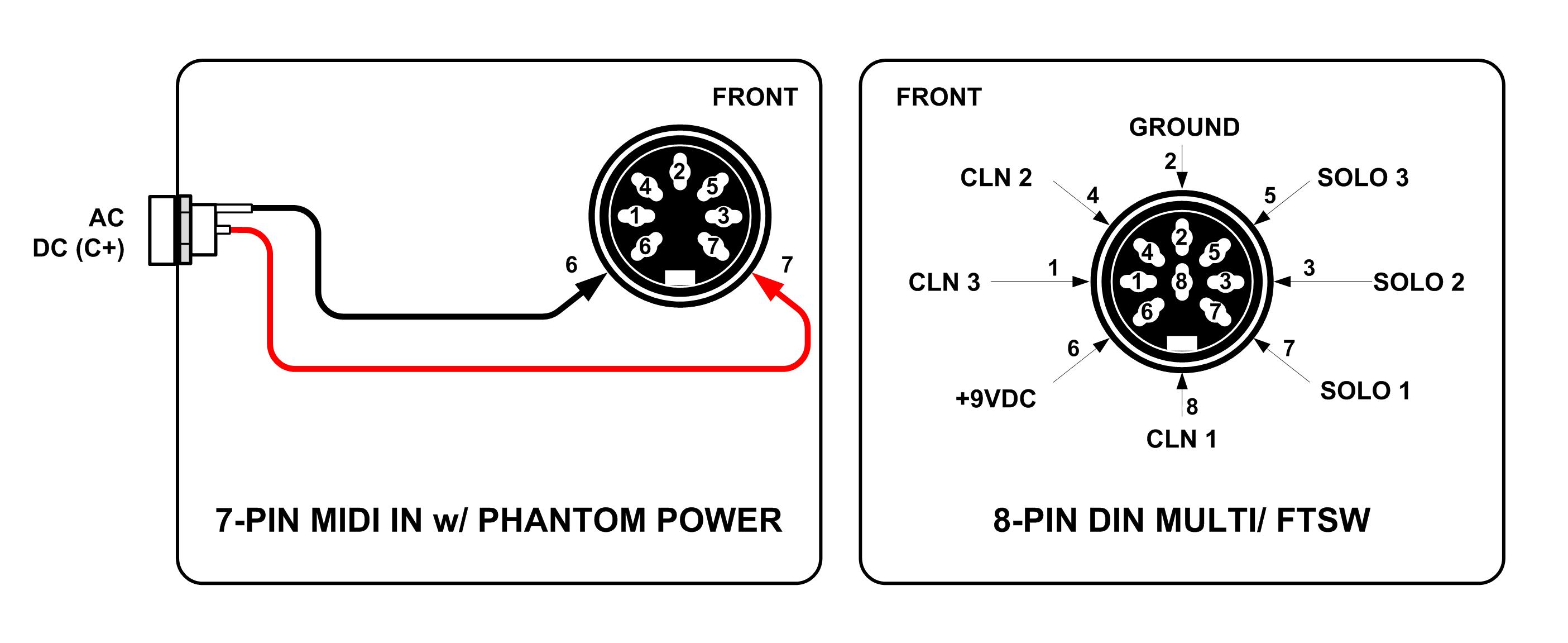
    The mute button is a non essential really but there for neatness. I have preamp diagrams and the standard footswitch wiring diagram. pages extracted from that here. No idea why it does not show Solo 2 and Clean 2 on top circuit diagram at right
    Beginner level experience – some soldering, wiring in past, computer builds.
    Click image for larger version

Name:	vtwinnedswitch b option ©  20210318  vt2c.jpg
Views:	1360
Size:	109.4 KB
ID:	926677Click image for larger version

Name:	vtwinnedswitch a ©  20210318  vt2c.jpg
Views:	948
Size:	127.4 KB
ID:	926678


  • #2
    The switch part is simple. The complication is the LEDs. Not too bad if you are willing to run a battery in the footswitch unit, but more difficult if you need to derive power from the preamp.
    Originally posted by Enzo
    I have a sign in my shop that says, "Never think up reasons not to check something."


    Comment


    • #3
      Could you post the rest of the schematic?

      The reason I ask is in looking at the arrangement for the 6 'optional external select' switches it's not clear (to me) whether the switches only affect the channel if it's already selected. It appears that besides the 6 switches you'll still need the clean/mix/solo switching. That would make 9 switches in total with the FX switch. The reason that clean 2 and solo 2 are not shown as outputs to the right is that they are logical states provided by the simultaneous outputs of Clean 1&3 and Solo 1&3 respectively.

      Comment


      • #4
        Originally posted by g1 View Post
        The switch part is simple. The complication is the LEDs. Not too bad if you are willing to run a battery in the footswitch unit, but more difficult if you need to derive power from the preamp.
        I am wondering if one of these would work for the footswitch just adding LED indicators for each switch button. It should be phantom powered from the pre amp same as the standard footswitch. I thought if i made those changes and altered the trs out from this unit to a din style (or other suitable) and constructed a box to sit in rack behind pre amp to connect to with a din in, and 6 1/4 outs to connect a standard TS cable in each to each pre channel socket on the pre amp.

        TC Helicon Switch 6 - 6-Button Footswitch


        Last edited by ctxuk; 03-20-2021, 02:32 AM.

        Comment


        • #5
          [QUOTE=Mick Bailey;n926838]Could you post the rest of the schematic?

          Sorry no, i cannot add any images it says i only have 47kb left. only have these in here already. cannot add to an album in media

          Seems i cannot add files and the add photos to an album instructs do not work either, ....

          going to your profile and clicking on the MEDIA tab. You will see all existing albums. Click on the thumbnail or title of the album you wish to add photos to.

          The album will open. Press the Add Photos button. On the new window press the Upload More button to get the file selection dialog box. Choose one or more files as usual to upload.


          no add photo button appears or the trashcan either. Probably something simple i am missing doing.
          Last edited by ctxuk; 03-20-2021, 03:08 AM.

          Comment


          • #6
            Someone here would need to confirm this, but I think the TC foot switches are momentary and they need to be latching for the purpose of building a simple pedal with DPDT switches.

            Also, bear in mind the switching would not be interactive like radio buttons - you'll have to turn off the selected function before selecting another on the same channel. It's possible to achieve this through logic gates (and momentary switches), but you'd have to build a much more involved circuit to do this.

            The standard Mesa foot switch isn't phantom powered as such - it uses the current passing through the LEDS to switch the channels and if you piggyback onto the supply, when you activate the 'other' LEDs you will unwanted channel switching. Any additional LEDs would need to be separately powered. In these situations I use a 9v battery and high efficiency, high brightness LEDS with a larger than usual series resistor. This brings down the brightness so that you can see them without getting dazzled, and extends the battery life considerably.

            I'll PM you with my email address and if you wish you can send me the schematics and I'll upload them.

            Comment


            • #7
              http://www.just-jamie.com/2015/02/07...h-6-schematic/

              Yes, seemingly they are SPST momentary in the Switch 6 unit. Shame as it at first look offers the chassis that is required for the build.

              In regards the leds, I bought a second footswitch that is a custom configuration made by Mesa for the Mesa V Twin with attached wiring not removable. I plugged that into the rear in one of the Solo 1/4 inputs, the standard identical one in the normal footswitch input and an FX Mesa (no led) unit in another channel in the rear in a clean channel 1/4 input. It selected channels on both extra footswitches and the lights on both my specific footswitches lit when channels were engaged, indicating no battery requirement perhaps.

              The schematic manual is here: https://www.google.com/url?sa=t&rct=...Xv3ig3Hzh1b8C8

              If I connect each of the 6 1/4 inputs into a custom box in the rack and from them to a din socket for the lead that also has two pins for the phantom power with the power augmented by the pedal power outputs from a racked G System it wouldn't require a battery in the footswitch or racked intermediary box would it?
              Last edited by ctxuk; 03-20-2021, 05:41 PM.

              Comment


              • #8
                The schematic cleans up the switching for the missing CLEAN 2 and SOLO 2, and it's as I previously mentioned in post #3.

                I can see how a Mesa foot switch wired with a series LED would operate with some of the 1/4" sockets, but not for the CLEAN 2 and SOLO 2 as there's no voltage present. There's roughly 5v on the others, fed via R136, R131, R140, R143 on the comparator inputs. You can use a 9v pedal supply output to power the LEDs via a DIN cable. I would do this for all of the 1-6 switches rather than rely on the comparator voltages.

                You say the foot switches select channels on both extra foot switches - did you verify the operation of the rear (1-6) inputs in combination with the regular foot switch input? I can't see how the CLEAN inputs would have any effect if you had the SOLO channel selected off the regular foot switch, and vice-versa.

                Comment


                • #9
                  Both rear connected switches operated, an on off for the channels they were plugged into. It may be though one was connected into a clean/solo 2 though. If I am beginning to understand correctly it would be far better to check operation with those inserted in either solo/clean 1 or 3 and have the toggle switches on the pre amp front panel in position 2 on both solo and clean channel. The existing regular footswitch was never removed and did operate on changes from solo to clean and the mix option of both channels together. The rear inserted switches were treated as being on/off switches only despite the extra options on one.

                  As I said previously I would look to put in a phantom power jack rather than use a battery. I can pull the power for this from either the G-System or a pedal power supply that I have in the rack setup. I figure it would do the same as using a battery without the hassle of changes when flat.

                  I found the below on a site called Stagecue where the person constructed a pedal unit for the vtwin. http://www.stagecue.com/vtwin.html
                  ........................................................ ........................................................ ........................................................ ........................................................ ........................................................ ........................................................ .......

                  The Rack-mount version has 2-Channels with 6-Modes… any of those channels/ modes are available and selectable separately via front-panel toggle switches or via six ¼” phone plug tip-to-ground contact closure connectors on the rear-panel. Those rear-panel connectors also allow you to mix Channel 1 modes with Channel 2 modes to get different sounds using an external control switcher and activating two of the Tip-to-ground contact closure connectors.

                  _________________________________________

                  External Control Switching Panel

                  This rear-panel Tip-to-ground connector panel was an option from MESA©, my second-hand preamp did not have the connector panel, just a blank cover plate, meaning that all channel switching had to be done manually from the front panel or with the included 2 button footswitch.

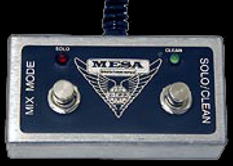
                  original footswitch image here


                  I fabricated a custom rear panel and installed a MIDI to Switch PCB for the MIDI Control of the V-Twin Modes. The rear panel includes a MIDI IN, MIDI THRU and an 8-pin MULTI Connector for connection of the below Custom Footswitch.

                  image of units here

                  A Phantom Power Jack connects DC on pin-6 and pin-7 of the 7-pin MIDI IN Jack to feed remote power to a MIDI Foot-Controller.


                  ​image of units here
                  photos here


                  _________________________________________

                  Custom Footswitch

                  This custom Footswitch allows the user to Mix Modes from the two Channels as well as allowing the user to Mute one or both Channels. It is Phantom Powered from the External Channel Select Panel 8-pin MULTI Connector.

                  ​image of completed units here which has 8 switches in two rows.

                  Comment


                  • #10
                    In addition to post #9

                    Whilst the Stagecue built unit features midi there is no midi on my VTwin and he put his own on there. The VTwin in itself has nothing operated via midi and no memory or patches to best my knowledge.

                    I do have a footswitcher though in the form of a Roland FC-200 which is connected to my Roland GP-100 and both have midi capability.

                    I think though it would be far simpler to have a separate switcher unit for the VTwin.

                    His unit appears to have the fourth switch as a disconnection device on each channel that also acts as the mix switch when both are engaged if I read what they wrote correctly. I had thought that engaging one switch on either solo 1, 2 or 3 would disengage the previous one automatically and in the same manner engaging one switch on either clean 1, 2 or 3 would disengage the previous one automatically with clean and solo being separate from each other in regard switching each selection but a mix switch added somehow. He added effectively two switches to give the mix capability which I guess would also act as a mute? Not sure how you could have no circuit engaged for any channel at all just using the input jacks with switching..

                    Comment


                    • #11
                      Originally posted by ctxuk View Post
                      Both rear connected switches operated, an on off for the channels they were plugged into. It may be though one was connected into a clean/solo 2 though.
                      That's what I'd expect - I was referring to the LEDs not working on the clean/solo 2 channels. I'd seen the Stagecue description but discounted it as a solution because his unit is midi equipped. A standard V-twin is indeed a 'dumb' unit with the mechanical switches being paralleled with JFETs in order to switch electronically.

                      With 6 independent foot switches there is no automatic disconnection of the previously selected function. This gives rise to 'illegal' combinations that are not usually possible off the front panel; Clean 1 + Clean 3 & Solo 1 + Solo 3. There is also no mute function that I can see. With all the 6 switches open you get the same functionality as if the switches are disconnected. You've probably figured this out - both front panel selector switches need to be in position 2 for the 6 switch inputs to work correctly.

                      Probably the best way to satisfy yourself of how a pedal will operate is to mount 6 cheap mini on/off toggle switches on a piece of board or metal and wire these to 6 1/4" plugs. This will replicate the functionality of a pedal and perhaps give rise to some further thinking before committing to building the actual pedal.

                      Comment


                      • #12
                        I just tested out what you are saying about the switching again.

                        A1 .....Normal pre amp specific pedal plugged into the footswitch jack socket.
                        A2......FX switch (no led) switch pedal plugged into the solo 1 jack socket.
                        A3......2nd Normal pre amp specific pedal plugged into the clean 1 jack socket.
                        Front toggle switches for solo and clean channels in position 2 on both.

                        I tested out by selecting clean on A1 and then switching A2 on and off, red led came up on A1 by itself (ie not mix as that shows both green and red leds)
                        I switched A1 to solo and then switched A3 on and off, that selected the green led on A3

                        I figure any led anomolies are due to lack of a Led on A2

                        You've probably figured this out - both front panel selector switches need to be in position 2 for the 6 switch inputs to work correctly.
                        No, but had figured after noticing the schematic showed no solo 2 or clean 2 on right of top schematic page they are the default positions.

                        Is there nothing available that would auto switch between 1 of three positions and an off position when engaging any of solo 1 solo 2 and solo 3, a second duplicate of that circuit for clean 1 clean 2 and clean 3?
                        Would I still require a mix of solo and clean switch in addition to these 6 swiches?

                        Comment


                        • #13
                          Originally posted by ctxuk View Post
                          Is there nothing available that would auto switch between 1 of three positions and an off position when engaging any of solo 1 solo 2 and solo 3, a second duplicate of that circuit for clean 1 clean 2 and clean 3?
                          Would I still require a mix of solo and clean switch in addition to these 6 swiches?
                          What you describe is radio button or interlocking functionality where selecting one deselects any other for Clean and Solo respectively. There are ways of doing this by using momentary switches along with logic gates and transistor switching, but it gets a lot more complicated. The simplest way is to use a microprocessor to control the switching, but that's another avenue where you'd need experience.

                          There is no function for an 'off' position in the schematic - effectively this is Clean 2 and Solo 2. You still need the clean/solo/mix switching - the 6 switch inputs only replicate what the front panel switches do and in themselves don't have any effect on the channel selection. You need 7 switches

                          Comment


                          • #14
                            I opened up the current footswitch to check the internals before ordering any items
                            resistors are 100 ohm with a 1% tolerance for the leds - brown-black-black-black - gap - brown , if that is I read it correctly. I would require a min of 8 of these, 1 each switch.
                            Do the led's themselves have a specific value? I could get 5v or 12v ones (thinking the schematic shows 5v around that area if I understand it correctly.

                            I think this is the required shopping list, please suggest changes if items incorrect, missing or not required.
                            Note decided may as well add the FX switcher to unit, So 8 buttons - 3 x Solo, 3 x Clean, 1 x FX and 1 x Mix Function.
                            Presumably in the din socket I can use the same ground for the FX switch as all others

                            2 Case box and cover +screws. 1 for inside rack, 1 for floor switcher
                            8 DPDT latching footswiches
                            6 1/4" Jack sockets (mono)
                            1 x 9v Pantom power jack socket
                            1 x 9v battery lead (in case phantom power fails operate.)
                            2 x 9 pin Din Multi FTSW
                            1 double end 9 pin Din Cable
                            6 mono TS cables x 1 metre
                            Wire - 3 colours - Gauge?
                            100 ohm 1% tolerance Resistors I would require a min of 8 of these, 1 each switch led.
                            8 leds and holders with 4 cols. 3 Red, 3 Green, 1 Amber 1 Blue

                            Comment


                            • #15
                              You won't be using 5v as the pedal supply is 9v. I buy regular LEDS - not ones with a specific voltage rating - and typically use 470R for a red LED or 1.8K upwards for high brightness blue or green. If you buy LEDs of the same type then the intensity is usually fairly even, so 470R would be my starting point. Stick to the Mesa 100R values for the clean and solo LEDs The reason not to use the 5v comparator supplies is you increase the risk of channel switching problems.

                              6 DPDT switches are needed for the external switching.
                              1 SPDT is needed for the clean/solo selection (I'd use another DPDT)
                              1 SPST switch is needed for the Mix selector, but I would just use another DPDT switch to simplify things.
                              1 DPDT switch is needed for the FX loop.

                              I prefer the Taiwan Alpha switches. I've installed plenty of these over the years and they've been reliable. Marshall uses them on many pedal assemblies. Rapid in the UK has them, amongst others.

                              I find locking D connector to be more reliable than DIN plugs and sockets, especially on a floor unit. Unless you use a locking DIN or other type of multi pin socket. The grounds are all common on the schematic. Wire gauge doesn't really come into it unless you have a really long run - look for something with good flexibility. You need 6 cable cores, plus 2 for the clean/solo select (the mix switch doesn't need an additional core), 1 for the FX and 1 for the common ground. I would use a screened cable to reduce the chances of interference causing unwanted channel switching. So, a 9 core screened cable. If you want to phantom power the LEDs you either need to run a separate cable or an additional core for the +9v (the 0v being connected to ground).

                              Comment

                              Working...
                              X