Ad Widget

Collapse

Announcement

Collapse
No announcement yet.

Weak tremolo in Gibson GA-40

Collapse
X
 
  • Filter
  • Time
  • Show
Clear All
new posts

  • Weak tremolo in Gibson GA-40

    Hoping someone can give me some guide here.

    I recently picked up a tweed 60-61 GA-40. Awesome amp but the tremolo is a bit "weak". Is it normally a subtle effect or should I look further, I'm using my Tremolux for comparison though I realise they are not the same circuit.

    The tube tests fine and strong so if there's an issue I'm guessing it may a resistor and/or capacior type problem.

    Any help much appreciated.

  • #2
    Hi,
    Is your amp a GA-40 or a GA-40T? I' m asking this because the two trem circuits differ, the first has a 6SQ7 with no LDR, the second has an 12AU7 with an LDR/lamp assembly.
    If you're positive the tubes are OK ( not only they should light up but their efficiency should be good as well ) check the components around the trem section, one of them could have gone off-spec weakening the trem ( e.g. resistors usually drift on the high side ). Also, if you have a GA-40T check the LDR, as the trem volume/intensity is greatly influenced by its efficiency.
    Hope this helps
    Best regards
    Bob
    Hoc unum scio: me nihil scire.

    Comment


    • #3
      Hi Bob,

      Mine uses the 6SQ7 valve. I've checked it on my valve tester so I'm confident that it's fine.

      Looks like I get to have some fun with the mutli-meter. Actually this works out well as I was thinking about making the groundswitch a stand-by instead as It is redundnat with a step down transformer so I was planning a bit of work anyway.

      Thanks for your response.

      Cheers,

      Mat

      Comment


      • #4
        Hi Mat,
        If you' re confident your 6SQ7 is OK ( does your valve meter measure efficiency-trans-conductance etc. or only the emission ? ), and the components are within their tolerance, I would try to clean/re-tension the tube socket(s), after all your amp is almost 50 years old, so the chances for a bad/oxidized socket are high....oxidized sockets add their resistance to the circuit so this could be the reason why the tremolo is weak.
        Hope this helps
        Best regards
        Bob
        Hoc unum scio: me nihil scire.

        Comment


        • #5
          Hi Bob,

          Good point about the sockets, I'll do all of them when I have the chassis out. A friend of mine currently has the amp to "test" it! So I'll go and wrest it back on the weekend and start working my way through it.

          Thanks again

          Cheers,

          Mat

          Comment


          • #6
            I'd suspect the resistors and capacitors of age related drift. Very common for tremolo problems...If the resistors are much more that 10% off change them and I'd change any electrolytics just because, unless you have a way to test them. If any of the coupoling caps are paper in beeswax they're suspect and likely bad. If they are later 50's production then check them for DC leakage-even a little will throw off subsequent stages....
            Got pics? I love seeing old amps naked.

            Marc

            Comment


            • #7
              Hi Marc,

              Once I get it back I'll try and post some amp porn for you

              Comment


              • #8
                I'd like to see the circuit board and layout too. I'm thinking about scratch building one of these cause I can't find anyone who makes a kit.

                Comment


                • #9
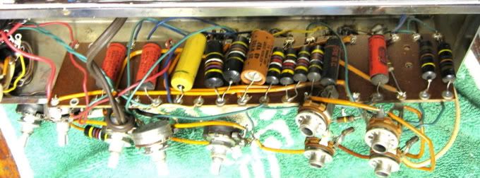
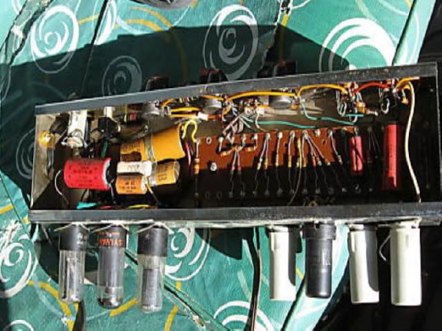
                  Hi Diablo; no kit that I know of and if the GA40's board is laid out like its little brother the GA20T Ranger (5879 in channel 2 with 6SQ7 oscillator), you'll need pics of both sides of the board. Channel 2 in the GA40 is laid out like channel 2 in the GA20 including a filtering array of Rs/Cs some / many of which are on the underside of the circuit board including several of the tremolo caps; like this -


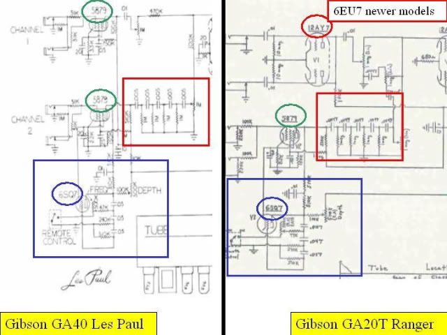
                  This GA20T matches the public domain schematic; when compared to the GA40LP, except for having a 12AY7 in the channel 1 preamp and minor component value deviations (ex; .0047 caps v. .005) and the location of the channel 1 volume control, the two schematics are identical. Anyway, if you're looking to leverage off the GA40 .... this pic will give you some idea of what you might be in for. Good luck and best wishes, CJ

                  Comment


                  • #10
                    Thanks CJ for the photo. I'm just going to have to draw up a layout when I get some time.

                    Comment


                    • #11
                      Hi Diablo; as Rod Serling used to say on Twilight Zone ... submitted for your consideration. Below is a comparison between the preamp of the GA40LP and the GA20T Ranger. As you can see, the only major difference is the 5879 in channel one and the 12AY7 in the GA20T. The LP's channel 2 has the same 6SQ7 tremolo tube and a filter of Rc/Csin the red box.


                      Below is a mod to bypass the R/C filter in channel 2 of the GA20T.


                      I don't know whether the two amps share the same transformer set; probably the power transformer (same rectf, same outputs) but maybe not the output transformer. My point is that unless you just have to have a 2nd channel but you really want to hear the 5879, considering a single channel 5879 / 6SQ7 / 12AX7 / 6V6s / 5Y3 amp; it's all you need. Channel 2 in my GA20T, except for maybe the output transformer, is electrically identical to channel 1 in a GA40LP ... a poor man's LP ... unless you really want 2 channels, it would be easier to do without the 2nd preamp tube. Good luck on your project. CJ

                      Comment


                      • #12
                        capnjuan, Don't want to hijack, but do you have pics of both sides of a stock circuit board for a GA20T? I have a friends' '56 here at the house that has had some work done in the last 20 years. There are some new filter caps and the tremelo footswitch is long gone. Actually, a pic of the whole chassis as you see it with the back removed would be great. The pic in this thread is a great help for the underside.

                        Thanks, Mike

                        Comment


                        • #13
                          Hi Mike: here you go!

                          Underside of board; the two large bumblebees in the middle now gone replaced with Mallory .047s; trem is perfect.


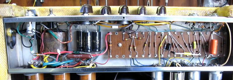
                          Top of board; original except: a) the 680ohm PI cathode resistor in the center has been bypassed with a 25uf/25V cap and b) the tone-killing R/C filter in channel 2 has been bypassed. In the upper left-center, there's a .01 cap tapping the signal from the plate of the 5879 and directly feeding the channel 2 volume control. The wiring was fed down an unused hole in the cb, across and up and 3) several resistors changed during trem hum chase. Otherwise, as original.


                          Full view of chassis; fresh ps caps racked in wiring strips and grounded separately. Because of the grid leak bias scheme in the preamp, these will hum like crazy if the center tap is left on pin 1. In the upper left-center, you can see the red/yellow heading to ground with the filter caps.


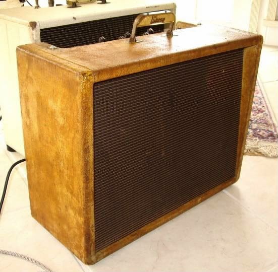
                          Showing off; the amp had been painted and between the surface prep for the paint and the stuff used to get it off, the outer layer of vinyl on the tolex gone. What was left was the cotton 'tweed' backing but the paint remover pulled the pigment out; left it like bleached cotton. The color is from diluted amber shellac used as 'sizing' and two coats of varnish ... "Buckaroo...."


                          Hope this helps! John
                          Last edited by capnjuan; 02-06-2009, 04:09 PM. Reason: typo

                          Comment


                          • #14
                            John,
                            Thank you very much! I hav'nt fired it up yet, so don't know if there are problems. There is/was some kind of waxy, dried, tan goo puddled on the rectifier V7, and 6v6 V6tube sockets. I've been trying to clean it up before checkout. some of the wiring for V7 that is laying in the chassis is stuck in this dried substance. I suspect some of the old caps will need to be replaced also. The goo that was on V6 had seeped through the socket and effectively "welded" the tube to the socket. I had to pry the tube loose!
                            Thanks again,
                            Mike

                            Comment


                            • #15
                              Hi Mike; before pic of my amp - it's the waxy potting around the outside of power supply filter caps dripping on the 6V6/5Y3 sockets at left. Because there was so little ventilation in these models, the transformers get hot and their potting oozes out too Alcohol will thin that stuff; Q-tips, dental picks ... yech ... this one wasn't so bad ...


                              Cheers! John

                              Comment

                              Working...
                              X