Ad Widget

Collapse

Announcement

Collapse
No announcement yet.

Twin Reverb Bias Confusion

Collapse
X
 
  • Filter
  • Time
  • Show
Clear All
new posts

  • Twin Reverb Bias Confusion

    First of all, I apologize because I'm almost certain this has probably been covered to death. But I have searched, and have not come up with a clear-cut answer to my question.

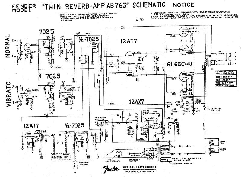
    I have a transition black line Silver-Face Twin Reverb. I call it a transition, because it came with an AB763 Tag in the cabinet, and a hodge-podge circuit which appeared to be a combination of the AB763 and the AC-568 schematics. The power supply and bias circuits were AC568, however none of the strange power tube capacitors were present in this amplifier.

    It has been less than reliable, so I stripped it to the chassis, and completely rebuilt it to AB763 specs, with a couple of minor mods including changes to the normal channel, and the addition of a dwell control to the reverb. To the best of my knowledge, these changes should have no effect on the power tube bias.

    I converted the bias pot to the AB763 arrangement. Biasing is such a grey area for me, and I'd like to correct that here.

    The AB763 Schematic specifies a voltage of -52V at the junction of the two 220K resistors that feed all the grids of the power tubes. I installed a 1 ohm resistor on one of the output tube cathodes (should I do this to all of them??) and measured the voltage to be around 10mV, for a current draw of around 10mA. This is with the voltage set to -52V per the schematic. Clearly this is way too low. Do I bother worrying about the voltage posted on the schematic?

    I have searched here and the internet like crazy, and I cannot find any specific suggested current to bias the tubes on the Twin. I have seen everything from 20mA to 35mA, which is a huge discrepancy. I can get it as high as 24mA before I run out of range on my pot. I will need to change the fixed resistor to deal with that, but then I will be very far away from the original -52V suggestion.

    Here's some other useful information: The B+ voltage on my amp is 435V, and the voltage at the plates of the output tubes is 408V on all four.

    Rumor has it the Twin was supposed to be rated at 80W, which to me means 20W per tube. If my Math is correct, 20/408 = 49mA.

    I read something about a 70% rule, regarding Class AB amplifiers. So if that has any weight, Assuming a 6L6 is a 25W tube, 25*.7 = 17.5W 17.5/408 seems like a more reasonable 42mA.

    Both 49mA and 43mA both greatly exceed the currents that I have seen suggested here and there, and rapidly bring that -52V closer to ground.

    What to do?!

  • #2
    OK, first, idle bias tube dissipation is a totally separate thing from output power. The 20 watts of dissipation at idle is not the 20 watts per tube of audio power. Much like the idle speed adjustment on my car does not determine how fast the car can go on the highway or how heavy a trailer it can pull.


    Unless you are using actual ancient 6L6 tubes, any current production 6L6 you buy is a 6L6GC and is a 30 watt tube for our calculations.

    You are looking too hard at the -50v, You haven;t mentioned what they schematic thinks the plate voltages outght to be.

    70% idle bias? 30w tube x 0.7 = 21 watts. NOT 20 watts as 1/4 of 80w. It is coinicidence the two numbers are similar. So 408v plates, P = VxI solving for I, I = P/V = 21/408 = 51ma.

    Maybe I am confused, but 408 seems a bit low for a Twin Reverb to me.

    Bias is explained in many places and in many ways. What you don;t need is an explanation that just says set it for this many mas. What you need is to learn what bias means, how it is calculated. Setting the bias on an amp to -51v is like telling someone they should drive their car around at 2200rpm on the motor, there needs to be a lot more information before we say that.

    You can mount one 1 ohm resistor for all four tubes and get an aggregate reading, or put on under each tube for separate radings. It won;t hurt it having only one socket with a sensing resistor, but that means you are assuming all the other tubes will be performing the same. Investing in four resistors allows you to compare readings between tubes.
    Education is what you're left with after you have forgotten what you have learned.

    Comment


    • #3
      Originally posted by akimball442 View Post
      ...Here's some other useful information: The B+ voltage on my amp is 435V, and the voltage at the plates of the output tubes is 408V on all four. ...
      In addition to Enzo's comments your B+ and plate voltages are not what I would expect. That's a 27 volt difference. I would expect something closer to 5V difference. What was the amp status when you took those readings?
      Tom

      Comment


      • #4
        Thanks for the replies. Using automotive lingo is always a plus, as automotive electronics is my job, and the only hobby bigger than my music would be my classic car habit.

        I think I found the discrepancy. This amp is quite a mongrel. Cabinet label said AB-763. I've read lots of those tags got out on later models, not worth really pondering further. Newest pot in the amp dated to the 20th week of 1968. Some pots date to 1967. I guess this might be a VERY early AC568, some hybrid circuit where someone did not get the memo! The only thing that matches the 568 is the power supply- the rest of the circuit was identical to the 763. The 568 Schematic I have is lousy, so I am including one for the AA769. The power supplies appear identical, and the voltages are in line with what I am seeing.

        They are considerably lower than the 763 schematic.

        I had a glitch. I must have measured the B+ with the standby switch shut off.... At that point the B+ measures 435V. Turn the switch on and it drops to 417V. Makes sense. There must have been a power transformer change between the 763 and the 568- the 763 calls for a B+ of 465V, and the 568 405V. Factor in my line voltage of 122V, and the 417V looks good.

        When I turn everything ON:

        I am getting a reading of 417V on the B+ and 416V at the plates. That sounds better than the 27V discrepancy that I had last night when I should have gone to bed. No more tired tinkering with high voltage for me.

        The later schematic suggests the bias voltage (I understand we don't care about the voltage that much, but it's a good baseline I would think..) should be -35V! That's not anywhere near -52V. Changing the fixed resistor on the bias pot to 10K gave me -35V in the middle of rotation.

        Back to using 30W as the base for a 6L6. 70% of that would be 21W. 21/416 = 50mA.

        Amazingly, set at exactly -35V, the current draw is 50.1mA!

        So did I get it right this time?

        By the way, the amp sounds GREAT. I think I know what the fuss is all about now. Would I gain anything by upgrading to the higher voltage transformer?

        Comment


        • #5
          Originally posted by akimball442 View Post
          ...Back to using 30W as the base for a 6L6. 70% of that would be 21W. 21/416 = 50mA. Amazingly, set at exactly -35V, the current draw is 50.1mA! So did I get it right this time? ...
          I say yes. Keep in mind however that you are not limited to setting dissipation at 70%. I wouldn’t go higher but you can experiment with lower setting and leave it wherever you like the sound best. I have found that many players choose a setting closer to 50% in a blind listening test.

          Originally posted by akimball442 View Post
          ...By the way, the amp sounds GREAT. ... Would I gain anything by upgrading to the higher voltage transformer?
          Unless you want more headroom / more output power I would not bother with replacing the PT. After all, you do think it sounds “GREAT”.

          The tolerance of the transformers used in Fender amps results in a wide variation in the resulting B+ voltage. It’s not that uncommon to find voltages in the range you measure in your amp. Your 416V is only ~8% below the Fender classic 450V B+.

          I recommend that you check the rectifier diodes for proper operation. I have found amps with one or more bad diodes and the amp was therefore running with half wave rectification. I even found one with a diode installed backwards at the factory and it had been that way all its life.

          Regards,
          Tom

          Comment


          • #6
            I checked the diodes and they all pass, so no worries there. And they are all oriented correctly. Funny that one survived for years with a backwards one, must have been built on a Friday afternoon after lunch.

            I'm pretty happy with the amp. The dwell control for the reverb is a huge improvement, and I like the tone stack mod I did to the normal channel. It's a tweed twin/bassman etc tone stack, no cathode follower or anything. I think the biggest improvement was increasing the bass pot to 1M and the mid control to 25K, it lets a lot more juice through and starts to grind nicely around 4-5 on the controls. Seems I don't really need the compressor in front of it anymore.

            Thanks for all the help!

            -Aaron

            Comment


            • #7
              Originally posted by akimball442 View Post
              I checked the diodes and they all pass, so no worries there. And they are all oriented correctly. Funny that one survived for years with a backwards one, must have been built on a Friday afternoon after lunch.
              The backwards diode is for the negative bias voltage, no?

              Comment


              • #8
                There are a total of seven. One is reversed to supply negative voltage to the bias, and the other six are to supply power to the rest of the amp. There are three in series on each of the PT secondaries tied together at the end of the 'chain.' See the schematics above.

                Comment


                • #9
                  I found a photo of the diode board in the amp I spoke about above. It is a 1969 Twin Reverb. It came to my shop in 2003 with a complaint of “Sounds weak/ sounds bad”.
                  The B+ was ~400V as received and the output started to clip at ~45W.
                  Based on the new cap installed we can see that it had been worked on since it left the factory. However, the diodes & their solder joints all looked original to me.
                  The lesson here is to check everything and keep your mind open to whatever you may find. It was good for the customer that he didn’t end up in one of those “ya need a new output transformer” shops.

                  Cheers,
                  Tom
                  Attached Files

                  Comment

                  Working...
                  X