Ad Widget

Collapse

Announcement

Collapse
No announcement yet.

Marshall 2098 Output Question

Collapse
X
 
  • Filter
  • Time
  • Show
Clear All
new posts

  • Marshall 2098 Output Question

    Hey Guys:

    I have a Marshall 2098 solid state amp that one of the low voltage Zener diodes (24V) went open. (unrelated fact)

    Previously someone went into the amp and replaced the output transistors.
    They also disconnected the ohms selector switch and "output" (or dampening transformer).

    The question is:
    1) If there is no speaker connected, does the ohm selector switch and impedance transformer act as a short circuit to ground?
    This would imply and the amp (like a tube amp) should not be operated without a speaker connected?

    2) Is it better to run the amp with the transformer connected or just leave it disconnected?

    Thanks ...
    Attached Files

  • #2
    It looks like an auto transformer. If it's not loaded I think it will behave more like an open circuit than a short circuit.

    Comment


    • #3
      Originally posted by TigerAmps View Post
      Hey Guys:

      I have a Marshall 2098 solid state amp that one of the low voltage Zener diodes (24V) went open. (unrelated fact)

      Previously someone went into the amp and replaced the output transistors.
      They also disconnected the ohms selector switch and "output" (or dampening transformer).

      The question is:
      1) If there is no speaker connected, does the ohm selector switch and impedance transformer act as a short circuit to ground?
      It is always a short circuit to ground for DC so you will not blow your speakers if the power amp blows/shorts.

      But for AC not only it is NOT a short, but a friggin' large inductor which will destroy transistors if unloaded, exact same as a conventional output transformer.
      Transistors don't know or care *how* it's wound, taps, etc, only that it's some 200 turns of enamelled wire wound around a couple pounds iron, the Mother of all output inductors.

      This would imply and the amp (like a tube amp) should not be operated without a speaker connected?
      Yes.

      2) Is it better to run the amp with the transformer connected or just leave it disconnected?
      It depends on the cabinet(s) you plan to use.
      The amp, as is, is a 100W into 4 ohms classic SS amplifier, in fact pulled straight from the Motorola Applications book.
      Notice all transistors suggested are Motorola types (nowadays: ON Semiconductor).
      If you will use it just with a 4 ohms cabinet, fine, you don't need the transformer ... although as said before it acts like a speaker DC protection, since it will short any DC to ground.
      But the beauty of that transformer is that you can use that head with 4 - 8 or 16 ohms loads and always get the full 100W on them (that's the idea)

      I'd ask you a favour, could you take and post a couple pictures? a full chassis guts one and a transformer closeup or two, I want to clone and test it.
      Would also need the EI core dimensions, from outside of course, as in:

      what on this example are 42.9 and 13.6 mm

      If pictures complicate your life, dimensions are enough.
      Thanks.

      EDIT: see the schematic footnote: the 2200 100W lead combo does not use the autotransformer nor selector ... because combos have a fixed cabinet attached and they made it 4 ohms ... now the head offered the same impedance flexibility as the tube heads, remembering that tons of Marshall 412 heads come wired to 16 ohms from factory.
      Last edited by J M Fahey; 01-25-2016, 06:12 PM.
      Juan Manuel Fahey

      Comment


      • #4
        Jaun - Thank you for the answer.

        I will take pictures and post them for you. I will also take the inductance readings between the taps as well.
        It appears to be an interesting/unique design. When you see the pictures, you can see it is a decent quality amp.

        I saw a guy use the bass version of the amp back in the early '80's. I have not seen another one until recently.

        Thanks Again,

        Keith

        Comment


        • #5
          Originally posted by J M Fahey View Post
          But for AC not only it is NOT a short, but a friggin' large inductor which will destroy transistors if unloaded, exact same as a conventional output transformer.
          It's driven from a low impedance. What happens to a mains transformer when the secondary isn't loaded?

          Comment


          • #6
            First Set Of Pics:

            Click image for larger version

Name:	106_1072.JPG
Views:	1
Size:	272.3 KB
ID:	840810
            Click image for larger version

Name:	106_1073.JPG
Views:	1
Size:	353.3 KB
ID:	840811
            Click image for larger version

Name:	106_1074.JPG
Views:	1
Size:	275.3 KB
ID:	840812
            Click image for larger version

Name:	106_1075.JPG
Views:	1
Size:	327.0 KB
ID:	840813
            Click image for larger version

Name:	106_1076.JPG
Views:	1
Size:	356.8 KB
ID:	840814
            Attached Files

            Comment


            • #7
              Second Set Of Files:
              Click image for larger version

Name:	106_1077.JPG
Views:	2
Size:	299.5 KB
ID:	840819
              Click image for larger version

Name:	106_1078.JPG
Views:	2
Size:	348.3 KB
ID:	840820
              Click image for larger version

Name:	106_1079.JPG
Views:	2
Size:	343.7 KB
ID:	840821
              Click image for larger version

Name:	106_1080.JPG
Views:	2
Size:	337.0 KB
ID:	840822
              Click image for larger version

Name:	106_1081.JPG
Views:	1
Size:	381.4 KB
ID:	840823

              The output transformer core size is: 3.0" X 2.5" X 1.0" Deep

              Inductance is:

              .028 H
              .068 H
              .130 H

              across the taps ....

              Keith

              Comment


              • #8
                Originally posted by TigerAmps View Post
                Second Set Of Files:

                The output transformer core size is: 3.0" X 2.5" X 1.0" Deep

                Inductance is:

                .028 H
                .068 H
                .130 H

                across the taps ....

                Keith
                Thanks a lot, just what the doctor ordered

                I have "cloned" them with absolutely no reference data, happy to see that I exactly guessed core size , now will wind another and measure inductance, that will tell me whether I properly guessed turns or not.
                Mine *do* work, but since in general designs you must accept compromises , sometimes you have to choose improving one parameter and inevitably lose on others.

                Extra turns mean better lows but less highs and viceversa, matching inductance will let me guess what did Marshal Engineers consider most important.

                I find the power transformer funny, with all that wasted window space.

                I guess they chose a larger EI size so they could stack less of it for the same core area, so it was "thinner" overall, sort of a "square toroidal" design if you catch my drift, to have it fit inside a thin case.

                Thanks again.

                ---------------------------------------
                It's driven from a low impedance.
                It's a low impedance as long as the amplifier is not saturated and NFB works it magic
                So you can safely make, say, a sinewave inverter with a 50/60 Hz oscillator, a power amp and an output transformer.
                You set level to just clipping, step down a little, and close the case.
                But this is a Guitar Amp.
                To Boot , a Rock guitar amp.
                Even worse, "it's a Marshall"
                First, transistors are very fragile, as they say "second breakdown turns 250W gorillas into 50W babies" .
                Reverse biasing while passing current is also very stressful, to say it mildly.
                Imagine, say, the top transistor with its base being driven , emitter reaching the +40V rail (it's being overdriven by the guitar signal) so it cuts off (base ceases being more positive than emitter and transistor cuts off, "the transistor switch opens", a regular SS amp would just clip there with no harm, but the brutal inductor connected to the emitter does not agree, keeps current constant and voltage rising.
                If no load (speaker) absorbs that energy, voltage will (try to) continue rising indefinitely ... in practice some 5 extra Volts until base-0emitter diode avalanches/"zeners" passing reverse current.
                Now that reverse current , different to forward biased one which evenly spreads across all of the die surface, concentrates on a few hotspots, it's way more destructive than what it seems on first sight.
                Not even need for an output transformer for that, even a large speaker voice coil, combined with a relatively large moving mass (equivalent to a mechanical inductor) does that, that's why many SS amps add clamping diodes, from speaker out to + and - rails.

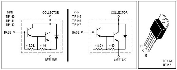
                In fact those Marshall transistors do have such a diode, built in.
                Not a high quality one, it's a parasite diode created when they diffuse a Darlington structure in the silicon, but better than nothing.
                TIP142/147 also have such built in diodes, always a source of confusion for unexperienced Techs who think their transistors are shorted.

                What happens to a mains transformer when the secondary isn't loaded?
                Nothing, but there you have an almost perfect sinewave, mains can take back and absorb anything you can throw it without damage, everything else connected to same line somewhare else *is* a load and in normal use there's no switching action.
                Yet when you switch a mains transformer on/off there is a spark, a voltage pulse, it gets injected in the mains line and sometimes pops somewhere else, etc. , so even there a switching action is not harmless or inconsequential.

                On an overdriven amp switching is what you have all the time.
                Juan Manuel Fahey

                Comment


                • #9
                  Thanks for taking the time and effort to write that Juan. I do appreciate it.

                  Originally posted by J M Fahey View Post
                  So you can safely make, say, a sinewave inverter with a 50/60 Hz oscillator, a power amp and an output transformer.
                  You set level to just clipping, step down a little, and close the case.
                  Yes, that's what I was thinking. Unloaded the small inductor current will follow the voltage 90deg behind. I'd never want to over drive a transistor output stage like that one and and for some reason I had it in my mind that it was a bass amp but Jack Bruce never got the memo about not over driving 100W Marshals did he?

                  Comment


                  • #10
                    Curiously two days ago I saw this in a German store. You might find interesting.
                    marshall 2098 - Onlineshop Startseite Tube Amp Doctor Onlineshop

                    Comment


                    • #11
                      Originally posted by Pedro Vecino View Post
                      Curiously two days ago I saw this in a German store. You might find interesting.
                      marshall 2098 - Onlineshop Startseite Tube Amp Doctor Onlineshop
                      Incredible !!!!!!!!
                      Funny thing is that the power transformer is good for *any* SS 100W@4 ohms amplifier and the autotransformer can turn *any* 100/4 amplifier , any brand, into a 4/8/16 ohms amp ... but nobody knows that so they will sit there collecting dust and rust forever
                      Juan Manuel Fahey

                      Comment


                      • #12
                        Juan:

                        Let me know how your hand made inductors compare - I am curious.

                        Another couple of questions:

                        Where do you get you transformer parts to make the matching transformer?
                        Do you use any special tools to wind them or do you do it by hand?

                        As the output transformer is disconnected, when I re-connect it, I'm guessing that I would have to reset the bias and DC offset?

                        The schematic shows 10mA measured at the Emitter of one of the output transistors.
                        How would I set the bias (which pot sets the bias)?
                        I would guess that the other pot adjusts the DC offset?

                        The first batch of parts are arriving today so I would like to put it back to "stock" configuration and fire it up over the weekend.

                        Thanks for all your info and help with this .... Super informative!

                        Comment


                        • #13
                          Originally posted by TigerAmps View Post
                          As the output transformer is disconnected, when I re-connect it, I'm guessing that I would have to reset the bias and DC offset?

                          The schematic shows 10mA measured at the Emitter of one of the output transistors.
                          How would I set the bias (which pot sets the bias)?
                          I would guess that the other pot adjusts the DC offset?
                          The bias pot is the one connected to the BC184K transistor base and 2k7 resistor. The other pot looks like it's for AC gain (it has a small cap in series). Is it the "Presence" control? I don't see a DC offset pot. The amplifier is unity gain at DC and the spec. for the offset voltage of the input pair is 15mV max so the output offset should be < 15mV.
                          Last edited by Dave H; 01-28-2016, 03:11 PM. Reason: typo

                          Comment


                          • #14
                            Hello folks,
                            I have one of these Marshall 2089's and am trying to determine something. This amp has straight bipolar T03 output transistors in it instead of the Darlingtons that apparently should be in it. (2SD424 & 2SB554 pretty common output xistors in 70's HIFI amps).
                            I'll be replacing them with the Darlington's, but as a curiosity, it seems to me that at the very least you would have to modify the circuit to deal with the smaller B-E drop as well as biasing issues & then at the very least the replacement transistors would need to have heftier current handling capabilities. Has anyone seen where a non-Darlington can be substituted for a Darlington? .
                            Also, the power transistors are drawing too much idle current and getting rather hot at idle.
                            This amp was donated to our store, so I have no history on it.
                            My gut says, this won't work.
                            Any ideas on subs for the original MJ3001 & MJ2501's?
                            I'm still trying to assess whether or not it's even worth repairing.
                            Thanx, Glen
                            Attached Files

                            Comment

                            Working...
                            X