 Tweet
Tweet
Originally posted by eschertron
View Post
-
AND... don't assume it ever worked at all in this configuration. I'm sure it worked when new... But, it is possible that someone simply replaced the field coil speaker with a permanent magnet type speaker, it didn't work, and then the amp spent the last 60 years in an attic. It takes a bit of knowledge and modification to convert an amp from field coil operation to a modern speaker. Definitely find or draw out a schematic before you turn it on. Also.. If that's a line level input, it's an extension amp. If it is an instrument/mic level input... It could have been for guitar, lap steel, accordion, PA, etc. -
I wonder why nobody "screamed"
LOSE THAT EXPOSED FUSE HOLDER ... NOW !!!!!
pull it now before you forget and turn amp on (you WILL, of course, the temptation is irresistible).
If nothing better, replace it with an internal, floating, in line type fuse holder which at least is plastic and has no exposed metal whatsoever.
 Juan Manuel Fahey
Comment
-
Sounds great. I will attempt to draw out the schematic in a legible way and post it. I hope someone can help me to decide just what it would be good for. I would greatly enjoy plugging my guitar into it. ThanksComment
-
So, you have a small pentode, a triode, and a large(ish) pentode. Sounds like you have a potential screamer. As Juan said, ditch that exposed fuse holder! Here's a great resource for the pins on your tubes:
Tubedata.org
Also, here:
Tubebooks.org
Some of the books from tubebooks are from the 40s, and will probably have some schematics for amps quite similar to yours. See how they drew them, and try to copy the style. Many of those books will have component diagrams, "this is a resistor, this is a transformer, etc." Do the best you can; if something doesn't make sense someone here will probably notice it & ask for more.
TAKE YOUR TIME, and don't rush. Yeah, I said that twice. Don't work when you're tired, impaired in any way, or distracted, either. Ask questions, do some research, and I bet you end up with a real beast of an amp. And, a better speaker WOULD help, but that's last...
Justin"Wow it's red! That doesn't look like the standard Marshall red. It's more like hooker lipstick/clown nose/poodle pecker red." - Chuck H. -
"Of course that means playing **LOUD** , best but useless solution to modern sissy snowflake players." - J.M. Fahey -
"All I ever managed to do with that amp was... kill small rodents within a 50 yard radius of my practice building." - Tone Meister -Comment
-
Perhaps post on a vintage USA radio forum, especially with that underside photo. The electrolytics and perhaps the resistors that are not 'dotted' may indicate an earliest date. The box electro's look like add ons. The front tolex style and pattern may be the best identifier - but could take years for someone to locate on a forum and associate. Perhaps try and get the images on Google image list.Comment
-
I doubt it has any collector value. But it has plenty of old cool value. I'd wager every cap in it needs to be replaced.
Looks like a field coil speaker to me as well.
It could be an old lap steel amp, but my first thought was the same as olddawg - movie projector speaker.
This is a pretty simple amp, so sit down with the tube manual for the base wiring of each tube you have, then drawing out a schematic from the chassis should not be a problem. You can look up how to read the color code on those old dog bone resistors.
I could be wrong, but if the amp was from the 1930s would it have all octal tubes? I'd expect more 4/5/6 pin bases.Education is what you're left with after you have forgotten what you have learned.Comment
-
Thanks guys. I do believe there has been some significant modification done. I have found some deleted wires and added caps and resistors. I will take a couple of weeks to research. Then I will start drawing the circuit. I will let yall know what I come up with. Thanks.Comment
-
If you want to reverse engineer the circuit more power to you! But as olddawg pointed in Post #16 we don't know if the amp ever worked at all (or properly) after the original field coil speaker was replaced.
I play lap steel and the old amps that are worth a lot are the "closet classics" that might have sat up in an attic for 50+ years and were never modified, except maybe to install a 3 prong power cable properly.
If it was mine I'd use it as a "donor amp", using the cabinet and metal chassis to build something like a 5F1 Champ amp from the 50's or one of the modified Epiphone Valve Junior amp designs from the past decade (these are both amps with a single control that can sound great.)
Steve Ahola
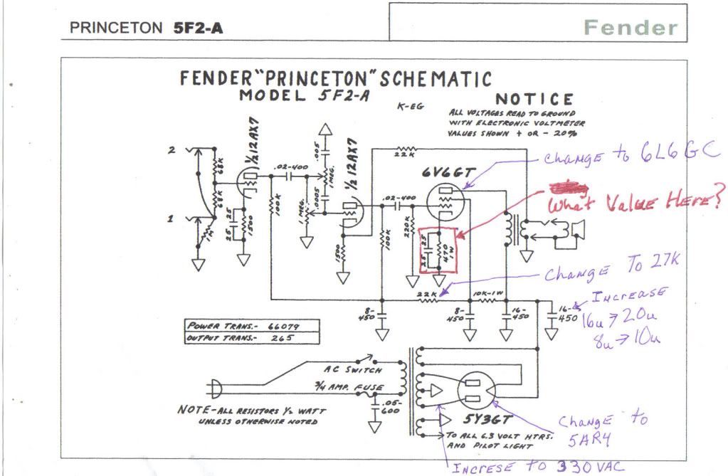
P.S. Actually if it were mine I would drill a hole for a second pot (tone)* and build a 5F2-A tweed Princeton clone - the preamp is basically half of a tweed Deluxe running into a 5 watt power amp.
Here are the tweed Champ, Princeton and Deluxe schematics, followed by two mods that look interesting.

%=%=%=%=%=%=%

%=%=%=%=%=%=%
%=%=%=%=%=%=%
%=%=%=%=%=%=%
 Last edited by Steve A.; 08-30-2016, 10:12 AM.The Blue Guitar
www.blueguitar.org
Some recordings:
https://soundcloud.com/sssteeve/sets...e-blue-guitar/
.Comment
-
I certainly like your idea, Steve. After looking at this amp last night and the modifications that I am certain have occurred I feel it would be over my head to reverse engineer. A good learning experience for me would be to start over with a known circuit. I will investigate more.Comment
-
I usually use donor amps for my builds because a cabinet and chassis usually cost at least $200 with shipping. BTW step drills work great in adding holes for 9 pin sockets if you can't find an octal adaptor mentioned in an earlier post. Make up a test cable with alligator clips and red, black and green rubber sleeves to measure the voltages of the power transformer disconnected from the existing circuit and post your findings here. You probably can't reuse it for most projects you'd want to build but it is worth a shot...Originally posted by heapes View Post
SteveThe Blue Guitar
www.blueguitar.org
Some recordings:
https://soundcloud.com/sssteeve/sets...e-blue-guitar/
.Comment
-
Steve, I sent you a private message. I am not certain it went through since it doesn't show in my sent messages box. If not I can retype.Originally posted by Steve A. View Post
Thanks for everyone's help.
StephenComment

Comment