Ad Widget

Collapse

Announcement

Collapse
No announcement yet.

Biasing a 1974 Fender SF Twin Reverb Master Volume Push Pull Switch - Reading 13 mA

Collapse
X
 
  • Filter
  • Time
  • Show
Clear All
new posts

  • Biasing a 1974 Fender SF Twin Reverb Master Volume Push Pull Switch - Reading 13 mA

    Hello all,

    my name is Federico, I live in San Francisco where I play guitar in a band called LoFi Satellites.

    Regardless of the statement in the band's name I do intend my gear to be at the top of their performance. That being said I have been "fighting" with a beautiful 1974 Fender Twin Reverb Silverface Master Volume Push Pull Switch.

    Schematic Fender 100 Watts RMS AMP w/ Reverb and Vibrato (the white schematic, not the blue one)

    After having changed the resistors in the Power tubes section by DALE's 1% 50 ppm (the 470 and 1,500 Ohm) and the rectifier section (new diodes) I have added the potentiometer on Rob Robinnette's mod to be able to adjust the BIAS Voltage while keeping the BALANCE potentiometer.
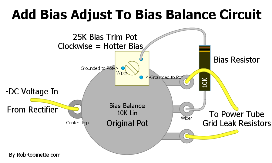


    After this mod I was able to set up the voltage so I got exactly -52V out of the balance potentiometer and -64V at the rectifier section with the plate voltage (pin 3 of the power tubes) was 450V (and balanced - same value - on the push an pull sides).


    Happy about how nice the voltages looked I bought the EUROTUBES Octal Bias Probe

    The current I've read was surprisingly low: 13 mA instead of the 39 mA I was expecting (the expected value comes from 25W/450V*70%*1,000)


    In the end I was happy with the good voltages at circuit level but not happy with how cold the tubes were running.

    I adjusted the added bias potentiometer until I got 38 mA reading at the bias probe (couldn't reach 39 mA). After that I disconnected the bias probe to re-measure the voltages on the circuit and i got -45V and -60V (instead of the nominal -52/-63V) with 439 V at pin 3 on the power tubes (whit that voltage I should have reached about 39.9 mA)

    Summarizing:


    My question is, what could be the reason why I get so low current into the power tubes when all voltages seem to be right on the circuit side?

    Thank you guys for your replies in advance, I've been following this forum for a while and it has been a great help on this project.

    Best,

    PS: to the possible question: "what do your ears tell you?" the answer is I prefer the right current in the tubes, however my engineering background keeps thinking why do I need to be 13% out of the nominal -52 V.
    Last edited by TelRay; 02-15-2019, 04:08 PM.

  • #2
    Why were you assuming a particular tube current would result from factory voltages? Tubes vary a lot tube to tube, so there is no voltage you can set that will always result in some particular current. The reason you got 13ma idle current is that that is what that particular set of tubes runs at with the given voltage.

    There is no "right current" in the tubes. There is what works well, and what does not. Nominal is just that, a named amount acting as an average point of reference.

    13ma would be dead on average for a Peavey 5150 stock amp, they all run cool.

    There is nothing precision here, it is just a guitar amp. Remember, your B+ voltage will change almost 4v for every volt the mains shifts. SO if mains goes from 120v to 125v, your B+ will rise close to 20v. And that certainly affects tube currents. The bias supply also grows at the same percentage, but the effect on currents does not track that.

    When I step on stage, it is my ears I aim to please, not a schematic. This schematic lacks the note, but MANY Fender schematics note right on them that voltages presented can be within +/-20%.

    70% is a rule of thumb from the internet, but is not designed into the amp. There is no way to engineer a particular current into it without a complex current sensing servo circuit.
    Education is what you're left with after you have forgotten what you have learned.

    Comment


    • #3
      I see you've got a matched quad set of J/J 6L6GC's, so, is your question how come when you began, with the bias voltage applied being -52V, you were only getting 13mA plate current and not your target of 39mA? Transconductance of the set of tubes you have. The plate current will vary based on that. Did you verify the rest of the 3 tubes were at/very close to that plate current on the one shown in the photo? I use the same J/J Apex-matched set in the Twins where I work, when I'm replacing the existing sets. I find with 39-40mA, you're pulling more like 145W at idle....which I think is a bit too hot....and run them around 33-34mA, idling around 124-128W. But, regardless of taste......am I correct in assuming once you got them biased up, all were running closely matched at that 38mA range?

      If with the mod and the tubes you're using, you can't get the current level you're seeking, I trim a resistor value in the bias LEVEL circuit to get there, so I have a comfortable min/max range to accommodate the tubes being used.
      Logic is an organized way of going wrong with confidence

      Comment


      • #4
        thank you very much guys for taking the time to go through my post and reply

        @ Enzo: “Why were you assuming a particular tube current would result from factory voltages?”
        i did not expect the reading to be dead on but something in the vecinity of the 39 mA (30-45 mA would have been 20% around this value). I was surprised to find it to be only 1/3 of that.

        @ Nevetslab: “is your question how come when you began, with the bias voltage applied being -52V, you were only getting 13mA plate current and not your target of 39mA?” yes, sir. that’s exactly my question.
        about yours on the readings on the other tubes, the curent values are:

        V7: 34 mA
        V8: 33 mA
        V9: 32 mA
        V10: 36 mA

        again, thx guys

        Comment


        • #5
          When you cranked up the current draw of the output tubes of coarse the supply voltage will drop from -64 to -60Vdc.

          It is not a 'regulated' power supply.

          Comment


          • #6
            @ Jazz P Bass: thx, I know that voltage would drop. I was providing it in the context of reference to what was changing after modifying the bias voltage
            thx again

            Comment


            • #7
              Originally posted by TelRay View Post
              ...The current I've read was surprisingly low: 13 mA instead of the 39 mA I was expecting (the expected value comes from 25W/450V*70%*1,000)...
              I don't think that your expectations are valid, as:-
              1/ You've not mentioned that you checked the mains voltage
              2/ Unless you have some inside info, I don't see why you should expect the amp's power tubes to idle at any particular plate dissipation; I suspect that the widespread nature of the rationale behind that is fairly recent, due to the internet.
              3/ The days when an industry body oversaw manufacturers to ensure that tube performance conformed to type bogey are long gone.

              If, with modern tubes, they aren't in cut off or redplating at the nominal schematic voltages, then that might be regarded as a win
              Last edited by pdf64; 02-15-2019, 08:42 PM.
              My band:- http://www.youtube.com/user/RedwingBand

              Comment


              • #8
                Agree with the others, your expectations are based on that 70% figure. That is a fairly recent internet 'interpretation' that only describes what a 'maximum' limit should be.
                Fender amps did not usually approach this figure, probably closer to 50 than 70%.
                So, the -52V number is a Fender number which has no association with the 70% figure that is bandied about.

                One thing that has not been mentioned is the screen voltage (pin4 of 6l6's) which will also greatly affect the idle current.

                P.S. I was just listening to 'deep', tell the bass player he needs more fuzz.
                Originally posted by Enzo
                I have a sign in my shop that says, "Never think up reasons not to check something."


                Comment


                • #9
                  @pdf64: thx for the reply! mains were at 120V. you are right, i understand the influence of this. and tube... yes, was lucky to find some NOS of 12AX7s (Sylvania and Tungsol) but not 6L6s.

                  @g1: interesting!
                  do i understand right and i should have expected to find something like 28 mA when the voltage was -52V? (25W/450V*50%*1,000)
                  or do you mean 28 mA is a target (being that 70% too hot for Fenders)?
                  yes, pin 4 was measured and it was 436V (when the tubes were at 38 mA) and were at 446 V (when i read the 13 mA). summarized below.


                  Ah... the Bass Distortion in "Deep" that was a matter of debate and there were a series of iterations (i'm not sure which one of those "iterations" have you witnessed... hahahaha)

                  Thank you guys for the input so far. Allow me to change the question a little bit.
                  What would be the current you would target to have on the tubes before plugin in the guitar and start ear-tuning to what sounds best?
                  And when reaching that value, how far from the -52 V would you be comfortable with before start thinking there's something wrong in the circuit (20%)?

                  Comment


                  • #10
                    should have expected to find something like 28 mA when the voltage was -52V?
                    Lose the idea of expecting ANY particular current. Old tubes, new tubes, any brand. Tubes all vary a great deal tube to tube, and they did even in the heyday of tubes. I have purchased new RCA matched pairs over the counter - many years ago of course. Said MP right on the box. If tubes were going to have predictable currents, we'd have no need for matching.

                    I don't speak for g1, but I think he was implying that 50% might be a better target for you than 70%.

                    how far from the -52 V would you be comfortable with before start thinking there's something wrong in the circuit (20%)?
                    I wouldn't sweat the voltage, in other words, the voltage we need for our operating point is the proper voltage. Yes, If I found it needed to be 80 or 15v, I'd sure be looking into why, but if I installed a particularly dull set of tubes that needed 45v, then so be it. Likewise if I needed 65v to tame a hot set, again, so be it.
                    Education is what you're left with after you have forgotten what you have learned.

                    Comment


                    • #11
                      I would guess that the -52V was a ballpark number that Fender used to get the tubes into the range they liked. And I believe that point would be closer to the 50% than the 70% idle dissipation figure. I also like the +/- 20% number that Enzo often refers to, and I think it gives a good range for that bias voltage.
                      Tubes do vary a lot in how hot they will idle for a given set bias voltage. Even more so in the modern era. So modern schematic are more likely to give a target voltage at the cathodes, which will tell us the idle current.

                      So back to the idea of 'what was the idle current Fender thought appropriate'?
                      I often fall back on the red knob "The Twin" from the late 80's, for 2 reasons.
                      a) it was a new product earlier in my career, so it stuck in my memory;
                      b) it was probably the first amp that Fender actually started measuring the cathode currents and provided test points for the user to do so, with rear panel trim pots for the adjustment of bias and balance.
                      Their 'number' was 40mV per pair, or 20mV per tube. That amp runs at around 475V on the plates, so you have around 9.5W idle per tube. That's about 32%.
                      We didn't get a lot of people complaining about bad tone. But now you've given the user something to play with, and they will.
                      So Fender got feedback from some, who stated the amp sounded better at hotter levels.
                      Hotter bias is a trade off, some tone gains for lower tube longevity.
                      The next iteration of the amp, 'Twin Amp', now had a suggested 'range' for the bias. 40mV (per pair) for longest tube life, 80 (pair) for 'best tone', 60 (pair) for compromise.
                      This works out to a range between approx. 32 and 64 % idle dissipation, with 64% being the high end.

                      For myself, I start around 60% and bring it down til I find the drop off in tone objectionable, then bring it back to where it sounds better again. Others will differ in how much tube life they are willing to trade off for tone, but I don't usually find the tone drops off badly until you are biased quite cold.
                      Originally posted by Enzo
                      I have a sign in my shop that says, "Never think up reasons not to check something."


                      Comment


                      • #12
                        thank you guys, this is really starting to look that a nice guideline. I really appreciate your (very educational) input.
                        Summarizing:

                        1) start with 60%
                        2) go down until you notice it's affecting the tone
                        3) check the bias voltage and if it's on the range of +/-25% of those -52V it's OK
                        4) if it's not start trouble shooting at circuit level, tubes, etc

                        if I could ask further, once these steps are finished and the values on each tube were 34, 33, 32, 36 mA would you consider those 34+/-2mA to be an acceptable range (variation from tube to tube) or would look for something more even?
                        If the answer is something like, I would look for 1 mA max difference between tubes I have no idea on how to do that apart from using the BALANCE knob which will balance the current by pairs of tubes (rather than individually).

                        Comment


                        • #13
                          First off, before I get an ear-full , the 'start at 60% and go down til it has a substantial impact on tone' idea is for higher power amps that are known to not be biased hot, the SF Twin being a good example. There are some brands and models that bias hot, and you would have to start with a higher number. Also, single ended amps (and some other class A) are generally run at around 100%.

                          A range within a few milliamps like you have is as good as you will get even with matched sets, so it sounds like you are pretty well matched. I always check all the screen resistors ( in this case 470R at pin 4) in any amp being serviced. Excess drift of these will have a noticeable effect on the idle current.
                          The matching pot on these was intended to help with hum, and adjusting by ear may be preferable to going by the numbers.
                          Originally posted by Enzo
                          I have a sign in my shop that says, "Never think up reasons not to check something."


                          Comment


                          • #14
                            Here is the truth about bias. COld enough to get excessive (objectionable amount) crossover distortion is too cold. Hot enough the tube plates start to get red hot is too hot. ANYTHING BETWEEN is just fine as long as you like the sound.

                            Honest, I don't start with ANY percentage. I set a reasonable bias voltage, say -50v, and see what happens. I then adjust it as performance needs. Stop worrying about percents of this and that, and tolerances of those and the others. Adjust it so it works. The amp is there to please your ears, it is not there to please a spread sheet.

                            Fender designed amps that should accept most any proper tube you install without going past the limits I described. They were not planning on 70% or 50%, that whole percent thing came along once the internet formed a community of amp tinkerers. They made amps you plugged four 6L6s into. If they wind up at 70% or 30%, as long as the amp worked, that was what mattered.
                            Education is what you're left with after you have forgotten what you have learned.

                            Comment


                            • #15
                              @ g1:

                              adding:

                              0) make sure your amp is "high power"
                              1) start with ...
                              2)....

                              hahahaha... thx man!

                              yes, I've changed the resistors in the Power tubes section by DALE's 1% 50 ppm (the 470 and 1,500 Ohm)
                              and btw, you asked me about pin 4 which I measured at 436V (when the tubes were at 38 mA) and were at 446 V (when i read the 13 mA). How can I use these values in this context?

                              Comment

                              Working...
                              X