Ad Widget

Collapse

Announcement

Collapse
No announcement yet.

anyone heard of a Dod 650?

Collapse
X
 
  • Filter
  • Time
  • Show
Clear All
new posts

  • anyone heard of a Dod 650?

    Hi new here,

    I recently re-discovered a board in my (small) collection & it says:

    DOD 650. The only chip on the board says MC1741CP 7719.

    If I remember it just boosted the signal.

    tried to google but, not too much info.

    Any information is helpful thanks!
  • #2
    1) A quick google indicates that the 650 was a "mini-amplifier", so I'm thinking some sort of headphone amp, OR possible a booster.

    2) The MC1741CP is simply a plain vanilla 741 op-amp (8-pin, right?) Are there any transistors on the board?

    Comment


    • #3
      Mark Hammer! it's an honor to have you reply to my question! thank you!

      I found the "mini-amplfier" thing too. maybe a booster? it was housed in the ol'
      mxr box but, years ago I took the paint off the box..

      yes, 8 pins & (forgive me I'm a novice) I don't see any transistors. 7 resistors, 2 more that appear gerainum, 2 disc caps, 2 light blue little cans (caps right?) & one flat green
      (cap?) & 2 pots. -- so that's 9 resistors, 5 caps & a 741 op-amp.

      any more help is appreciated!

      Comment


      • #4
        Go here http://filters.muziq.be/model/dod/first and take a look through the various DOD pedals listed, especially the pics of the boards.

        In the absence of any additional transistors (something I might expect if the 741 was essentially providing a little boost prior to a pair of transistors kicking the signal up to earphone levels), the chances are good this was some sort of successor to the DOD 250 ( http://filters.muziq.be/model/dod/first/250 ).

        And while we're at it, any chance that the "650" might actually be a "250" that has been worn down in ways that could lead the eye to treat a 2 as a 6? I ask because the list of components you provide is VERY similar to what's found on a 250.

        Comment


        • #5
          I checked the links. maybe that's the guts of the next generation 250 (the yellow one)? and maybe I have the 1st generation 250?

          It certainly says 650. maybe it's a 250 using a 650 board? I can't be a 100% certain but, I think the box was the original color scheme of the 250 (gray-ish & yellow).

          I posted some not so perfect pics in the pic section. would you mind taking a look?

          http://music-electronics-forum.com/a...&pictureid=185

          http://music-electronics-forum.com/a...&pictureid=186
          Last edited by tboy; 03-30-2009, 09:32 PM.

          Comment


          • #6
            Okay. very helpful pictures. It's a distortion circuit. The "back-to-back" pair of diodes going to ground (the two red things in the upper left of the component-side picture) give it away. This unit is VERY similar to an MXR Distortion+ and DOD 250. Compare the parts layout on your board with thias schematic: http://www.generalguitargadgets.com/...ist_250_sc.pdf

            In the picture where you show the pots, the pot at the bottom is a distortion control. I can tell because it connects to the 4.7k resistor (yellow-purple-red) and cap in series (let me guess, it says either 473 or .047, right?).

            The other pot is the output volume control. The green wire connected to the middle pad for the volume pot is the output wire, and the brown wire is ground. T'wer I, it'd be green or black, more commonly chosen colours for ground, but if you have a green already...

            Unless I am mistaken, the "empty" pad just adjacent to the ceramic capacitor that is slightly obscured by the brown wire is the input pad. Check the components against the schematic linked to above, and I think you'll be okay.

            Some recommendations:
            1) Too much fizz. Stick a 47pf capacitor in parallel with the 1M (brown-black-green) resistor. Consider replacing the 1000pf green cap with a higher value unit, like .0022uf-.0033uf. I wouldn't go much higher than .0033uf unless you like it really warm with little edge.

            2) Not enough distortion, even at max. Replace the 4k7 resistor (yellow-purple-red) with a 3k3 (orange-orange-red) resistor.

            3) Too thin at higher gain. Replace the .047uf cap going to the distortion pot with a unit between 0.1uf and 0.22uf to let more bass through.

            Comment


            • #7
              great! I didn't see the value 473 but, I'll continue to compare the schematic & wire this sucker up.

              still curious why the board says 650 but, it wouldn't be the first time a fly ended up in the soup.

              thanks for your time Mark!

              Comment


              • #8
                Well, whatever the value of that flat ceramic cap in the upper right hand corner, between the 4k7 resistor and distortion control, might be let me know.

                One of the problems with googling DOD pedals is that DOD also happens to be the initials of the Department of Defense!

                So, I popped off this note to DOD just now, and hope to get some response from them. naturally, if I get a reply, I'll post it here.

                "I was recently asked by someone to help them repair a DOD 650 pedal. At least that is what it said on the board. The circuit seems suspiciously like that of a DOD 250. What exactly WAS the 650 pedal?

                Thanks for your help."

                Comment


                • #9
                  Well THAT was fast!

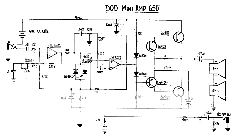
                  Just got a note from DOD support with the schematic of the 650 as a PDF, and it was pretty much exactly what I thought it was in the first place (prior to seeing the pictures), and the reason why I asked about transistors. It was a mini amplifier that, according to the schematic, had three controls - gain, tone, volume - and used a simple 4-transistor push-pull amplifier to power two small speakers. It ran off 6AA cells (9v). The confusing thing is that it used a TL072 dual op-amp, and not single op-amps like the 741.

                  Is it possible there is a second board with the little 4-transistor power-amp section?

                  Unfortunately, I can't post things from work, but I'll post the schematic later this evening. Alternatively, give me your e-mail address and I'll send it to you.

                  Comment


                  • #10
                    whoa! Awesome work Mark!

                    but..now I'm really confused! wouldn't that mean 3 knobs? & the different op amp?

                    I'm fairly certain that it only had the one board. However there was no bottom plate to the box. The guitar store I purchased it from said he got it at a swap meet deal (wish we still had those!) & all I had to do was wired it up. which I did & it worked..

                    also, after re-reading your post I looked at the cap (I think your asking about) & it says .05 up. does that make sense?

                    I also just sent you a private message with my email..

                    Thanks a bunch Mark!

                    Comment


                    • #11
                      .05 = .047 in the real world.

                      Yeah, this thing has me really confused. The front end really IS a DOD250, but you don't seem to have the other half, and there is no indication that the board has been damaged or chopped in any way.

                      Anyway, for interested parties, here is the schematic. FWIW, I'm not so sure it is entirely accurate, even though it came directly from DOD.:

                      Comment


                      • #12
                        WOW! & WOW! I'm such a novice.. (.05=.047)..

                        I just rechecked the board & there doesn't see to be any extra cuts. seems clean.

                        I'm going to review both this schematic & the 250 with a (experienced) friend & if interested I'll post the results. This may take a few weeks.

                        One final note and it probably doesn't matter, I did notice the box it came in is slightly larger than a MXR distortion box I have. It's the same style box otherwise.

                        Comment


                        • #13
                          Somebody on the DIY Stompbox forum posted a link to this e-bay ad this morning with tons of inside and outside photos. http://cgi.ebay.com/ws/eBayISAPI.dll...ayphotohosting

                          Here is what the inside of an actual DOD 650 should look like.

                          As you can plainly see, this looks nothing like the board you have. So I'm both mystified and intrigued. The board you have plainly indicates 650, but the circuit it contains is way more 250 than 650. Seems to me this is some sort of transitional item. I guess the best path to take is to treat it as if it were a 250, and make it functional.

                          Comment


                          • #14
                            I don't know much but, that's not what I have! - I have to admit, I never thought in a million years I could mystify you! -- I hope my electronically savvy pal can have a look at this soon!

                            If memory serves me, it was functional, I just can't remember how funtional. Obviously it wasn't impressive because I didn't play it again & forgot about it till now.

                            I wonder if it has more value without it modded? though..the case is trashed. damn.
                            after my friend looks at it I'll post the parts & values. and who knows maybe it sounds
                            cooler through his vintage fender & marshalls.

                            Comment


                            • #15
                              The board is definitely from a 1977 grey Dod 250 Overdrive/Preamp.

                              For comparision purposes you will find the guts of two 1976 Dod 250 below:


                              analogguru

                              Comment

                              Working...
                              X