Announcement

Collapse
No announcement yet.

wanna help me figure out how to true-bypass a dean markley overlord?

Collapse
X
 
  • Filter
  • Time
  • Show
Clear All
new posts

  • wanna help me figure out how to true-bypass a dean markley overlord?

    the bypass on this pedal is so terrible. i'd like to true bypass
    it, but i'm unsure on how to rig the pedal up so that the circuit
    if always on. i know how to wire a mechanical switch for true bypass,
    that parts easy.
    but rigging the circuit to always be on after removing the soft switch,
    that's where i need some help. i've got a schematic if anyone needs to
    see it, let me know. thanks guys.

  • #2
    Go here: http://www.diystompboxes.com/wiki/in..._AND_SWITCHING

    Comment


    • #3
      thanks for the link, mark. but unless i missed something, i know how to true-bypass a pedal w/ a mechanical switch. i understand switch theory and how to wire it all. what i need to figure out is how to replace a momentary soft-switch w/ a true-bypass hard switch, which that article doesn't seem to cover.
      the overlord uses a momentary soft switch to ground a point on the board to turn the pedal on or off. the point on the board is only grounded when the switch is depressed. so it's not as easy as, "when this point is grounded, the pedal is on".
      i've heard there's a FET involved w/ the switching. but after some continuity tests, i can't conclusively figure out how to ground or jumper the FET to keep the circuit on. if i could keep the circuit on all the time, i could route the signal through or around the circuit via the switch which would give me true bypass. then i'd simply have to rewire the LED through the switch, (which would probably mean cutting a trace or two) and i'd be done.
      anyone have any more advice? thanks again.

      Comment


      • #4
        Please do post the schem, maybe we can be of more help then.
        Happy new Year!

        Comment


        • #5
          The pedal will use some kind of flip-flop to convert the momentary switch electronically to a toggle action. You need to hack the flip-flop circuit so it's wedged in the "ON" state permanently. If you post a schematic, I can help you out.
          "Enzo, I see that you replied parasitic oscillations. Is that a hypothesis? Or is that your amazing metal band I should check out?"

          Comment


          • #6
            Okay. I get it now.
            Is it this pedal? http://filters.muziq.be/model/deanmarkley/overlord

            If so, then the power supply is turned on separately. What sort of switching arrangement is used can be quite different. The manual for the pedal (http://www.deanmarkley.com/Info/Lega...uals/D1020.pdf) indicates that it uses a momentary switch, which indicates a flip-flop somewhere in there, as Steve suggests. Of course, what that flip-flop does is another matter. It could actuate a relay (and wall power makes this a possibility), it could actuate a CMOS switch, or it could do the "Boss thing" and actuate some JFETs. Hard to tell from here. I guess what we need is more info about the parts in it. Doesn't necessarily have to be a full schematic, just something that provides some idea of what exactly is doing the switching in an electronic sense.

            E.g., are there any 14 or 16-pin chips in there that have a CD or MC prefix or a number starting with 40 or 140? Are there any transistors in there with a K or BF in the part number? Is there anything that doesn't look at all like a chip (i.e., a relay)?

            Comment


            • #7
              ok everybody, here's a schematic. i hope the quality is good enough.
              steve - i believe you are correct. the flip-flop needs to be hacked. that's what i can't figure out. i need to make the pedal permanantly "on", and use the new 3PDT switch i'm installing to route the input signal through the circuit or straight to the output jack. everything aside from hacking the flip-flop i have covered.
              mark - that is the correct pedal you linked to. as mentioned above, i need to hack the flip-flop. there is one FET in the pedal which i believe to be the area needing attention. all i've done so far is turned the pedal on and measured every pin of the FET for continuity to ground and continuity to another leg of the FET. i compared that info to the same measurements taken w/ the pedal off. (by "on" and "off" i mean "not bypassed" or "bypassed"...i'm not talking about the power switch.)
              the tests i did proved nothing. i was hoping for a simple, "jump this" or "ground that". any thoughts?
              BTW...my copy of this schem is a photocopy of someone's photocopy. at some point the two LED's were highlighted, and of course on my copy that appears as a greyish/blackish area...which of course means it appears completely blacked out in the scan. the blacked out part near p7 of IC2 is just the green LED. (bypassed or not bypassed). the blacked out part between the transformer and the tube is the red LED. (power "on").

              Comment


              • #8
                Seems to me that all you have to do is remove Q1 and Q2. The pedal is always on, the signal gets routed differently depending on wether it is bypassed or not. By removing the Q's you're forcing the signal to go just the "effected" way. So all you have to do is make the"effected" path switchable with a 3PDT and wire the bypass LED accordingly. I hope this makes sense to you.
                But please expect confirmation from Mark and Steve, just to be on the safe side, before you do any work on it.
                This pedal seems like a copy/license of the B.K. Butler pedals.

                Comment


                • #9
                  The schematic shows the following. In one "state", Q2 goes low-resistance, which means that the gain of the inverting stage where the Drive control is is reduced to essentially zero. At the same time, Q1 also goes low resistance, meaning that there is a low-resistance path from the C3/R3/R4 junction to output resistor R11. When the state is reversed, the resistance of Q2 goes high and is in parallel with VR4, setting the gain (Drive) of that stage. At the same time, Q1 also goes high resistance, placing a very high-resistance path for the "clean" signal to get through to the output.

                  So, it disables the effect by dropping the tubes' input signal down to nil, and allowing muchmuch more of the clean signal to reach the output. I can see why this is something you'd prefer to truly bypass, since any residual hiss from the tube side of things is always mixed in to the output. I don't know how noisy the tube side is, but whatever noise IS there, you're likely gonna hear it.

                  To have a true bypass of the circuit, you would do the following:
                  1) Unsolder Q1 and just yank it right out of there OR, take your utility knife and cut the trace between R2/R4 and the FET.
                  2) Take Q2 right out of there.
                  3) Wire up a stompswitch with C1 going to the switch's input lug and R12 going to the output.

                  Note that since the Overlord assumed that all switching would be done within the circuit/pedal, there is no terminating resistor on input cap C1. This will result in audible popping when your switch is installed. To eliminate popping, stick a 1M resistor from the "free" end of C1 to ground.

                  There are, apparently, better and worse ways of wiring up the heater in the tube, which can impact on how much hum isproduced. I can't tell from the drawing whether this has been taken advantage of or not.

                  If you rotate the drawing 90 degrees clockwise, you'll see there is a strong resemblance between the the tone control arrangement and the standard Fender/Marshall tonestack. Should you wish to tailor the tone control to your own particular needs, I suggest that you take a look at on-ine resources regarding those two tonestacks, and also at the online Duncan Tonestack calculator.

                  Thanks for scoring the schem. Another one to add to the stack!

                  Comment


                  • #10
                    so mark...all i have to do is remove Q1 and Q2? and the pedal will be permanently "on"?
                    that seems too easy. i thought for sure i would have to jumper something.
                    as for the green LED, i'll just lift the (-) and route it to the switch w/ a limiting resistor to ground.
                    the schematic was hard to find. i found a guy online who scored it a few years back from someone HE found online. and up until i scanned and posted it, it was strictly a paper transaction. i got my copy of a copy through the mail. hopefully it will be easy to find online now for anyone who may be looking.

                    Comment


                    • #11
                      Sounds like win-win for everyone. And yes, removing the two FETs makes it permanently "on". Since I could not see anything in the scheme that looked like a flip-flop, you can satisfy my curiosity by telling me if the stock footswitch is a (nonclicking) momentary or is a latching/clicking SPST like some sort of table lamp switch.

                      Comment


                      • #12
                        hey mark, the stock switch is a non-clicking momentary. thanks for the help, i'll try to mod the pedal this evening and post results.

                        Comment


                        • #13
                          hey mark...i removed Q1. there is no Q2.
                          if you look more closely at the schem, (as i should have) you can see that the three pins of Q1 (marked, "S", "D", and "G") are labled as such:
                          in the upper part of the schematic, "D" is on the left and in the lower part of the schem "D" is on the right.
                          "S" is on the right in the upper part, but on the left in the lower part.
                          "G" is in the middle on both drawings.

                          anyway...i removed the FET, but the pedal switches exactly as it used to. i haven't listened to the pedal since removing the FET. i wonder if the gain will be different now?
                          i'm going to try jumpering SW2.(momentary switch) it's in between pin 7 and pin 6 of IC2. R8 comes off pin 6 to the switch, and R9 comes off pn 7 to the switch.
                          let me know if you have any other ideas. thanks again.

                          Comment


                          • #14
                            The orientation of the S and D of an FET used in this way doesn't matter at all. It's like water going through a pipe, it will always go through no matter which end you feed it.
                            What I'm thinking is that maybe you don't have the right schem. It's either other pedal or a diff revision of the same pedal.
                            According to your schem there should be a second Q somewhere.
                            As I said in a previous post, this pedal looks like a copy/license of the B.K. Butler pedals, so there is a possibility that a schem for one of his pedals will match yours.

                            Comment


                            • #15
                              no...i dont think so. what i was saying is that my pedal only has ONE fet. and the schematic i posted also only has ONE fet. it's just drawn twice to show how it's hooked up to each IC. the fact that there is a reference letter "A" to show that those parts are connected and it was drawn in after the fact let's you know that my schem is obviously a photocopy. 
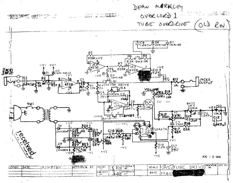
i haven't traced the circuit out entirely, but it looks correct to me w/ the pedal in front of me everything has checked out so far.

                              Comment

                              Working...
                              X