Announcement

Collapse
No announcement yet.

Piezo Opamp design

Collapse
X
 
  • Filter
  • Time
  • Show
Clear All
new posts

  • Piezo Opamp design

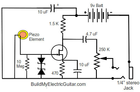
    Let me preface this by stating im a newbe at solid state design. I've built my own overdrive pedal that works great but to be honest I don't have a firm grasp on what every component does. I have a very simple and cheap piezo pickup that i am trying to amplify for use with guitar. I am using a 9v battery, a 4558 opamp, and a guitar jack output. I am going for the most simple/least components design. What I have right now works pretty good, I just need some help in fine-tuning. Here is the schematic I designed. piezopreamp.gif picture by Prattacaster - Photobucket
    I actually have a 100uf cap on the positive voltage to smooth DC, it isnt shown on the schematic. Things I would like to see improved (in order of importance) are:
    1) Resonates much more on certain notes, mostly being the Low E string and one octave above that, it does this regardless of placement and guitar used; electric or acoustic.
    2) A little noisy overall
    3) Mids are a bit nasally. Seems to be around 800-1k freq. I turn the mids down on my amp but the "mid-hump" is still there. I would say its upper mids, not quite to treble frequencies but close.
    4) Slightly low gain, not to bad tho.
    If i could fix these issues it would sound awesome, and i would be much appreciative.

  • #2
    The schematic doesn't look right, can you check it over? eg why 2 caps in series at input, is op-amp configured as inverting or non-inverting, whichever it is what are you doing with the other input? Pete.
    My band:- http://www.youtube.com/user/RedwingBand

    Comment


    • #3
      Its an AC coupled opamp??? Pin 3 is supposed to be grounded, one flaw in the design amoungst others i'm sure. The .001 cap; The original design had a 470k resistor in series between the .001 and the 1uF cap. The amp didn't work with the resistor in there so I just snipped it out. I was trying to make a high pass filter and thats how I was instructed to do it, I quickly realized it was wrong. A resistor to ground is what is needed in between these to caps, right?

      Comment


      • #4
        What you got there has the makings of an op-amp differentiator Operational amplifier applications - Wikipedia, the free encyclopedia
        but as neither input has a dc bias reference, I'm not sure how it's working?
        The circuit gain would increase - to massive amounts - with frequency.
        Piezos normally require very high input impedance, eg several M ohms, so discrete FET buffers are often used.
        My band:- http://www.youtube.com/user/RedwingBand

        Comment


        • #5
          I need to add a 1 meg resistor after the .001 input cap? or totally redesign? I don't think it was working, at least it wasn't pulling any current because I left the battery plugged in overnight a couple of times and it still has plenty of juice.

          Comment


          • #6
            I don't think that a piezo pickup buffer is a good application for a 4558 op amp.
            I'd try a simple JFET buffer, along the lines of
            Get Better Sound from Piezo Mics & Pickups: Get proper Bass with Piezo Contact Mics and Piezo Guitar Pickups
            My band:- http://www.youtube.com/user/RedwingBand

            Comment


            • #7
              I think it's supposed to be a charge amplifier or something?

              I've had poor results with charge amplifiers myself. I think they can go unstable and resonate at some frequencies as mentioned in the original post. The regular high-impedance buffer circuit as shown above is probably a safer bet.
              "Enzo, I see that you replied parasitic oscillations. Is that a hypothesis? Or is that your amazing metal band I should check out?"

              Comment


              • #8
                I agree with pdf64. I too am in the process of coming up with a preamp for a piezo pickup. Per the article that he mentions, I can attest to what is being said there.

                In my case, I used piezo coax as the pickup (for a mandolin) and ran it directly into my amp. Not only was the volume very low, it had no bass and sounded terrible.

                So I built a preamp based on this circuit, which uses a MPF102 (easily purchased from radio shack):
                FET Preamplifier, part 2

                The sound was MUCH better / fuller, and natural sounding. However there was still not enough gain, so I added a 10uF tantalum cap across R3, which helped, and I used a 10 meg for R1 (it was what I had..) but I think I am going to have to build a two stage preamp circuit.

                Hopefully this weekend I will be able to do that. I will let you all know my results.
                My Geeky blog:
                MikesTechBlog.com


                Building my Electric Guitar:
                BuildMyElectricGuitar.com

                Comment


                • #9
                  OK sorry for taking a long time in getting back to this, there was this thing called life that sorta got in the way.

                  Anyway, here is the completed schematic of the jfet preamp I am using using the MPF102 Jfet:


                  Here is an article that explains this Jfet preamplifier circuit.

                  -- Mike
                  My Geeky blog:
                  MikesTechBlog.com


                  Building my Electric Guitar:
                  BuildMyElectricGuitar.com

                  Comment

                  Working...
                  X