Ad Widget

Collapse

Announcement

Collapse
No announcement yet.

How do you Fix a Pulled up Trase on PCB

Collapse
X
 
  • Filter
  • Time
  • Show
Clear All
new posts

  • How do you Fix a Pulled up Trase on PCB

    I was working on a 1985 Ibanez Metal Screamer and 3 of the trases have pulled away just from light heating Is there away to fix,or do I need to run long leads down to next point on the board

  • #2
    Bummer, we've all done it you can carefully stick them down with super glue, gently burnish any broken parts with very fine sand paper (400 or higher) or 0000 steel wool, and re-solder together.
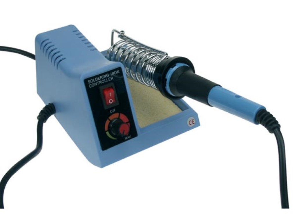
    Get an adjustable small iron and use just enough heat to flow good fine electrical solder!


    if traces are GONE you will need fine wire jumpers,

    Comment


    • #3
      Yes, basically that, only I suggest Epoxy instead of SuperGlue.
      Juan Manuel Fahey

      Comment


      • #4
        3M has stick on copper pads and traces.
        You heat it with the iron, and it bonds permanently.

        Comment


        • #5
          Originally posted by tedmich View Post
          Bummer, we've all done it you can carefully stick them down with super glue, gently burnish any broken parts with very fine sand paper (400 or higher) or 0000 steel wool, and re-solder together.

          Get an adjustable small iron and use just enough heat to flow good fine electrical solder!


          if traces are GONE you will need fine wire jumpers,
          what kind of wire is that. I can't belive how easy they lifted up. 3 seconds at 30 watts poof

          Comment


          • #6
            Originally posted by dumbassbob View Post
            what kind of wire is that. I can't belive how easy they lifted up. 3 seconds at 30 watts poof
            I don't know what kind of wire tedmich used but I have two spools of tinned bus wire- one 22GA and the other 24GA. I've had them for almost 30 years now and they come in handy for all sorts of repairs. A broken knob on your stove? I will wrap the tinned bus wire around the plastic bush that goes on the shaft and then solidify it with solder.
            I would like to get something even smaller for tiny traces (the 24GA works fine for guitar amps) so perhaps someone here knows of a source.

            Steve Ahola

            P.S. After experimenting with different mods on my PV Classic 30 and other amps a good number of the traces were completely gone. I'd recreate the circuit with component leads if I could, or use the jumper wire. I've also used solder wick and copper foil tape (soldered and epoxied.)
            BTW I found one tool to be very helpful when removing resistors or small capacitors- it is one of those dental picks intended for soldering. The one with the right angle tip works very well in pulling the component lead straight up from the copper pad. As in tedmich's picture you want a small iron with an adjustable wattage output. They are much cheaper than the thermostatically controlled solder stations- but they work better for fine work. (A thermostatically controlled iron always draws the same wattage when it cycles on so it can fry small components and boards.)
            The Blue Guitar
            www.blueguitar.org
            Some recordings:
            https://soundcloud.com/sssteeve/sets...e-blue-guitar/
            .

            Comment


            • #7
              thanks,One other thing ..Can I put a electrolytic cap where a metal film caps was I want to make myMIT DS1 like a MIJ?

              Comment


              • #8
                It depends where the cap is used.
                If it is a coupling cap, yeah.
                Mount the electrolytic cap so the signal goes into the negative & out of the positive.

                Comment


                • #9
                  Mount the electrolytic cap so the signal goes into the negative & out of the positive.
                  ¿?????????????
                  Don't think caps (even electrolytics) are unidirectional, with respect to signals.
                  I'd rather worry about the DC voltage they are meant to block.

                  Another doubt: what does MIT and MIJ mean?

                  Yet another: if they mean electrically different versions, can you please post the schematics?
                  Juan Manuel Fahey

                  Comment


                  • #10
                    made in taiwan

                    made in japan

                    Comment


                    • #11
                      [QUOTE=J M Fahey;277920]¿?????????????
                      Don't think caps (even electrolytics) are unidirectional, with respect to signals.
                      I'd rather worry about the DC voltage they are meant to block.QUOTE]
                      Juan, I was simply indicating what I see in oh so many amps.
                      Actually I was trying to head off "which way does it get installed".
                      Yeah, Made In Taiwan or Japan.
                      I don't know exactly what it is that is different but the MIT is scorned.

                      Comment


                      • #12
                        Originally posted by Jazz P Bass View Post
                        It depends where the cap is used.
                        If it is a coupling cap, yeah.
                        Mount the electrolytic cap so the signal goes into the negative & out of the positive.
                        On the board it is C-8,and they said to make it like a MIJ to put a metal electolytic cap in the one in there now is a .047uf.I just wanted to know If it was OK to put a electrolytic in where a regular NP Cap had been...

                        Comment


                        • #13
                          Originally posted by Jazz P Bass View Post
                          It depends where the cap is used.
                          If it is a coupling cap, yeah.
                          Mount the electrolytic cap so the signal goes into the negative & out of the positive.
                          Thanks,I would of done it wrong and put positive first....I have slowly been modding some of my OD,and Distortion pedals,and they do sound better....Mainly I just changed the caps to Metal films and GE Diode's....T

                          Comment


                          • #14
                            Boss DS-1

                            Well now C8 appears to go to ground.
                            That is why I asked 'how is it used'?
                            In that case the negative goes to ground.
                            The schemes that I have seen show C8 as a 0.47uf/50V capacitor (not 0.047uf)
                            For the life of me I cannot see what that will do to the circuit (adding an Electrolytic Cap)
                            Attached Files

                            Comment


                            • #15
                              Thanks,I would of done it wrong and put positive first
                              Please, stop talking about "first" or "last".
                              You must know which pad is more positive and which is more negative, and orient it accordingly.
                              By itself, "input" and "output" is irrelevant.
                              In this simplest possible amplification stage (EH LPB1 , a clean booster), you have 2 caps, C1 and C2 in the audio path.
                              *These* are non polarized, but suppose you replaced them with 2 electrolytics (what you did in your pedal).
                              Signal flow *as drawn*, goes from left to right.
                              So ....... should you place positive on each left pin, according to the theory just mentioned?
                              Well, no.
                              C1 needs its "first" (leftmost) leg negative ; C2 its "first" (leftmost) leg positive.
                              Why?
                              Because C1 is connected from ground potential to (positive) Base biasing voltage; while C2 is connected from Collector (positive) voltage to ground voltage.
                              Click image for larger version

Name:	am1.gif
Views:	1
Size:	7.5 KB
ID:	827003

                              And in the pedal?
                              Who knows?, we have not seen a schematic yet nor which capacitor we are talking about.

                              EDIT: OOOOPS !!! Simulposting !!!!
                              Dear JPB, thanks a lot for making things clear and by posting the schematic.
                              Sorry for what I wrote above but I was getting nervous about this excellent Forum becoming like "My Les Paul" or countless other ones out there.
                              And yes, I also fail to see what magic purposes might come by replacing C8 by a same value electrolytic.
                              That said, I think the .47uF value drawn is wrong; .047 sounds more logical ; let me check with a reliable schematic, I'll be back.

                              EDIT2: finally, I found a Factory original schematic.
                              Well, they seem to have chosen to use a *big* cap in the main gain/feedback loop.
                              Now I understand comments in some forums which call this pedal somewhat "muddy".
                              Too much pre-distortion bass. Oh well.
                              Click image for larger version

Name:	Boss_DS1_PG2.jpg
Views:	1
Size:	206.4 KB
ID:	827004
                              They show C8 as a 1uF cap, and *already* polarized, meaning an electrolytic.
                              Polarity seems to be marked on the PCB itself.
                              And in this particular point , there's neither "first" nor "last"; it bleeds some feedback signal to ground to make the stage amplify.
                              Although we still have one leg more positive than the other.

                              Other point: yesterday I was looking at MIT and MIJ boards, side by side.
                              They were *exactly* the same (up to Board and revision number, etc.), same parts values; only some caps colour or brands varied, what's normal in any product depending on the "supplier of the day":
                              Why one should be dissed and the other praised, escapes me big way.
                              Even more: "modding one into the other" means nothing

                              I , for one, keep Religion at Church and Physics at the Lab ; lately it looks like things are seen the opposite way.
                              Too many "faith" based opinions without corresponding physical evidence backing them.
                              Oh well, Brave New World.
                              Last edited by J M Fahey; 10-04-2012, 03:12 AM.
                              Juan Manuel Fahey

                              Comment

                              Working...
                              X