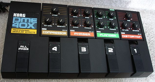
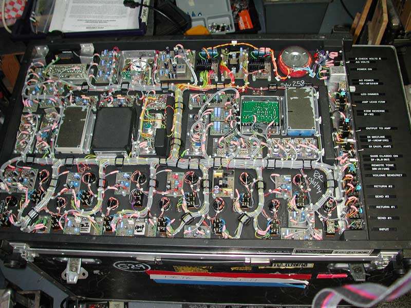
I'm trying to downsize my pedalboard and consolidate some of my pedals, several to one box, via one input and output jack and one DC 9v in - in the top of each pedal, so that they can all be mounted flush, up against each other.
I've realised that I could actually fit two to three pedals into each 1590BB enclosure to reduce the size, amount of cable connectors and weight.
This would make for a way more compact board as well as many pedals have PSU or in/out jacks inconveniently placed and reboxing in this fashion would make for way more efficient space management. (I've attached photos to illustrate the possibilities, though not necessarily what I'll actually utilise).
Though I'm pretty handy with a soldering iron, I'm not an electronic engineer, or even to work my way around a schematic and everything I've built has been from graphic illustrations or photos.
So what I need help with is how to connect the internal wiring so that each pedal runs from right to left, into it's neighbour, but remains totally out of circuit (true bypassed) when switched off.
They would also need to be powered from the one DC 9v in.
I'm sure that this is all relatively straightforward with the right skill set.
And help or advice would be gratefully accepted!
Thank you!


.jpg)


Comment