Announcement

Collapse
No announcement yet.

Anyone familiar with the Addrock Ol' Yeller overdrive?

Collapse
X
 
  • Filter
  • Time
  • Show
Clear All
new posts

  • Anyone familiar with the Addrock Ol' Yeller overdrive?

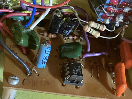
    Recently acquired a very early one that looks like a project/prototype and it's easily the smoothest sounding overdrive pedal I've ever heard. I don't have tons of experience with pedals but I do have plenty of experience hearing things and this thing is extremely pleasing to the ears.

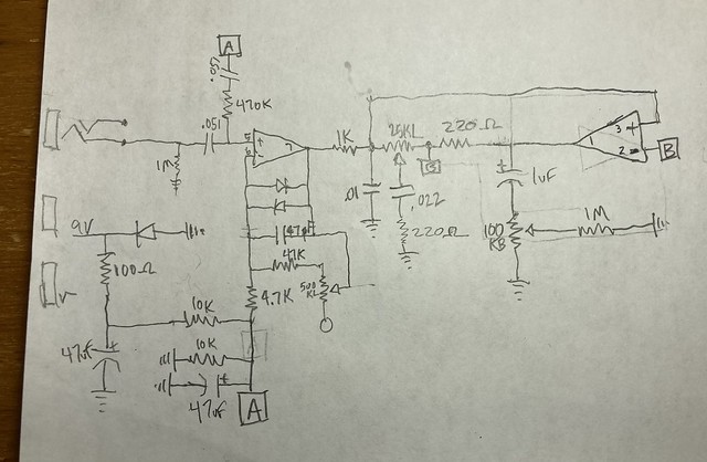
    It sounds so good I'm inspired to build a couple dozen of them as a project. Haven't drawn out the schematic yet but here's the parts list, straight from the pedal.

    It sounds tube screamery but better... smoother.. any idea if this might be a straight copy of something that came before it? recognize the recipe?

    Thanks for any info, thoughts or comments... they are all welcomed.

    47uF 50v (2)
    .22uF 50v (1)
    .1uF 100v (1)
    1uF 50v (1)
    .051uF ?v (2)

    1M (2)
    10k (2)
    100r (1)
    47k (1)
    4.7k (1)
    470k (1)
    220r (2)
    1k (1)

    4580D op amp

    1N914 (3)

    25kL pot
    100kL pot
    500kL pot

    open jack (1)
    stereo jack (1) (what's the point of a stereo jack when using mono cables??)
    9 pole switch
    LED
    Power jack
    Battery clip


    ~Semi-No0b Hobbyist~

  • #2
    Originally posted by mort View Post
    stereo jack (1) (what's the point of a stereo jack when using mono cables??)
    Usually to disconnect the battery when the cable is removed, so battery is not being drained when pedal is not in use. The battery (-) wire connects to the ring terminal. When you plug a mono cable in, ring gets connected to sleeve (ground).
    Originally posted by Enzo
    I have a sign in my shop that says, "Never think up reasons not to check something."


    Comment


    • #3
      Interesting that they used a 4580 op amp.
      (or was that slapped in a a later time)
      They can be a tad power hungry.

      Comment


      • #4
        I'm just guessing but its probably op amp diode clipping and the "smooth " is in the tone shaping components . Can you trace it out ?

        Comment


        • #5
          About Addrock ol' yeller

          https://www.thegearpage.net/board/index.php?threads/addrock-ol-yeller.648033/

          https://reverb.com/item/6214890-addrock-ol-yeller-overdrive-pedal-808-tube-screamer
          It's All Over Now

          Comment


          • #6
            Originally posted by 35L6 View Post
            Can you trace it out ?
            You mean make a drawing of the circuit? I plan to and will update the thread when it's complete.

            ~Semi-No0b Hobbyist~

            Comment


            • #7
              Oh man what an old thing you have, I hope you figure out how to work with it)))

              Comment


              • #8
                Originally posted by dmeek
                From photos I've found here's the schematic
                That looks like a phaser, not an overdrice. Also the 4580 only has 2 opamp sections.
                I guess it's more like a Tubescreamer without the switching Fets.
                - Own Opinions Only -

                Comment


                • #9
                  Ok I think I got everything into the drawing except the power connections for the op amp, LED, output connection and power jack but the main circuit I think is complete.

                  Does it look like it has errors in it?

                  ~Semi-No0b Hobbyist~

                  Comment


                  • #10
                    Not that it isn't easy enough to figure out and generally assumed, but ground symbols on the jacks are missing and the ground switching circuit on the input jack isn't shown (+ wrong ring/tip for input). None are major issues, IMO. Just pointing it out.
                    "I took a photo of my ohm meter... It didn't help." Enzo 8/20/22

                    Comment


                    • #11
                      Yup I gotcha and always appreciated.

                      The main point of the exercise is to prepare for having some boards made up.

                      I'm going to go through it again a couple more times but thought I'd throw the drawing up now that it's on paper.
                      ~Semi-No0b Hobbyist~

                      Comment


                      • #12
                        Also, where's the output? I think you've got something drawn wrong on that second op amp.
                        "I took a photo of my ohm meter... It didn't help." Enzo 8/20/22

                        Comment


                        • #13
                          Ah good catch. The output is on the wiper of the 100k pot. I've added it to my drawing and will update the thread later after more refinement.
                          ~Semi-No0b Hobbyist~

                          Comment


                          • #14
                            And what was that schematic drawing software that can be used for having pcb's made up? I had it on an old computer and only ever used it for drawings.
                            ~Semi-No0b Hobbyist~

                            Comment


                            • #15
                              I see 2 problems The 470K resistor from pin 5 needs to go directly to point A. The 220 ohm feedback resistor on the second op-amp should be 2.2K or 22K?
                              I've re-drawn it in a more conventional layout.

                              Click image for larger version  Name:	51235073198_951f0ba86d_z.jpg Views:	0 Size:	20.0 KB ID:	934129
                              Click image for larger version  Name:	scan0001.gif Views:	0 Size:	126.6 KB ID:	934131
                              Last edited by dmeek; 06-09-2021, 03:39 AM.

                              Comment

                              Working...
                              X