Ad Widget

Collapse

Announcement

Collapse
No announcement yet.

Tone Pots: Linear or Audio? Why?

Collapse
X
 
  • Filter
  • Time
  • Show
Clear All
new posts

  • #61
    Last one for awhile (I keep forgetting things). I also wanted to know if there's any value in getting digitially metered and "matched sets" of pots, like here:

    The Hoagland Brothers Guitar Company || Pickerington, Ohio || potentiometers

    Does it make a difference? Again, thanks.

    Comment


    • #62
      Originally posted by David Schwab View Post
      We wouldn't need a VCF... why voltage control? There's no need for it. They use VCF in analog synths because the whole system works on voltage control, including the oscillators.
      I'm actually in the process of modding my guitar so that the tone knob sends a control voltage to a VCF in a pedal so that I have a tone control I will actually want to use. And, since that knob is only sending a control voltage, it could conceivably control anything else which accepts a CV input.

      So suppose you have a low pass filter installed with a frequency knob. How do you want the knob's taper? If the control goes from 500 Hz to 5KHz, you want the rotation of the knob to evenly distribute the cutoff frequency.
      Well, you might, but I don't. Neither does anybody who uses a VCF, apparently, because every one I've seen uses an exponentiator circuit to drive the filter. Without the exponentiator circuit, if you just wanted to control with a pot, you'd have to use an exponential taper to approximate the same response. With a linear response, the filter would be too tweaky to use in the lower range of the rotation, and sound like it was doing almost nothing in the upper end of the rotation.

      It's quite possible we hear frequency-dependent amplitude differently from overall amplitude such that for a graphic EQ a linear taper is appropriate.

      Comment


      • #63
        First, The treble bleed cap and resistor TV Jones is recommending is for the Volume control. It maintains the treble response as you roll down the volume pot. the Resister changes the taper or sweep of the pot. The idea is to maintain better control of the rolloff. This is not the Tone control cap on the tone pot. Which feeds the signal to the pot to ground.

        My opinion is : I do not like the cap resistor mod to the Volume pot. Tried it many times many ways on many guitars, Not for me. I am old school and actually use the Volume pot to control the tone a bit as well. Also, For me I find it very important to have a good quality pot Of The AUDIO taper for the volume control. The best I have found are PEC available at Antique Radio supply. But others like the custom CTS pots from RS guitars and others.

        Others like the Linear pots for volume. From a theoretical point it should work, but in real life does not and that is precisely why the Audio( or LOG) taper pots were invented. They work more like the human ear hears. IE, at half volume the pot should be on 1/2 rotation. But the taper is subjective and there is a quality control factor to getting it right.

        And your outcome will depend on how you use the volume control. If you tend to run it on 10 all the time, then it won't make too much difference what you use.

        The cap and resistor mod is easy to do and remove or test it out. so see if you like it. I find most people just like the idea of a MOD, good or bad, useful or not.

        Others will chime in and tell you to use a LINEAR pot for volume. My best advice then would be, try them both and see for yourself what you like best. There is no Wrong answer.

        Comment


        • #64
          WOW, So many questions, ha ha.

          It is not common to use linear pot for tone controls. Gibson does it on some of their newer Les Pauls and it sucks.

          I don't think you will hear any difference with a metal film resistor at that level of voltage. But they are cheap use them if that is what you have, I use Carbon Comp , because they sound better in guitar amps and I build and repair a lot of them. I also use metal film in a few pedals I build, they are smaller, but CC works just as well.

          Try the vitamin T's, I have used them in a few amps and had too many fail, I think they are chinese or russian. I would not expect them to fail in a guitar though. I don't think you will hear any benefit over a good film and foil cap like Spargue(vishay/SBE) or mallory 150.

          I had a friend who had Collings build him a few electric guitars, on one he had them put in all PEC pots Audio 500k, and Jupitor caps. He said it was very noticeable the improvement in tone , control and feel of the electronics.

          Good luck on your journey, I hope others will chime in with their experiences and preferences/ thoughts.

          Comment


          • #65
            Originally posted by uvacom View Post
            I'm actually in the process of modding my guitar so that the tone knob sends a control voltage to a VCF in a pedal so that I have a tone control I will actually want to use. And, since that knob is only sending a control voltage, it could conceivably control anything else which accepts a CV input.
            Or you can build a low pass filter into your guitar, and not need the control voltage. Like Alembic does.

            Well, you might, but I don't. Neither does anybody who uses a VCF, apparently, because every one I've seen uses an exponentiator circuit to drive the filter.
            Wow, that's really presumptuous. You know EVERY person who uses filters? I use filters, and they all have linear frequency response. That's everything from the filters in my Oberheim Matrix 6, to the state variable filter I built back in 1976 that I used to run my bass through. So I have been one of THOSE people for a long time.

            Filters don't change the AMPLITUDE of the signal, they change the cutoff frequency of the filter. In the case of a low pass filter, you are removing the treble frequencies, but not lowering their amplitude. They just aren't there. So you would not need or want a log taper pot, unless you want most of the rotation to only handle something like 50 to 60 Hz, and the rest in then crammed in the last 10 percent of the rotation. What good is that? Go play with the filters on something like a Mini Moog, and you will see they are linear, with the frequencies evenly distributed across the rotation, like the face of a clock. Voltage controlled circuits need the exponential control to work in a linear fashion.

            Log taper pots are made to hear an even sweep of the amplitude of a signal.

            Now look at a standard state variable filter design (not voltage controlled). They use dual ganged pots to control the CF. These pots are linear. See the example below from an Alembic Series II preamp.

            Without the exponentiator circuit, if you just wanted to control with a pot, you'd have to use an exponential taper to approximate the same response. With a linear response, the filter would be too tweaky to use in the lower range of the rotation, and sound like it was doing almost nothing in the upper end of the rotation.
            You are describing log taper. If a filter goes from say 0Hz to 100Hz, you want the half way point to be 50 Hz. How is that tweaky? Tweaky is having the last half of the frequency range crammed between 8 and 10. You would never be able to hone in on a frequency range.

            Voltage controlled synths needed exponential voltage, but that's because of the design of the oscillators and filters, not because it was needed for the way it sounds.

            It's quite possible we hear frequency-dependent amplitude differently from overall amplitude such that for a graphic EQ a linear taper is appropriate.
            No we don't. If you listen to a keyboard playing a waveform with few harmonics, all the notes sound the same volume.

            Look up some non voltage controlled filter designs, like this one I picked at random:

            http://servv89pn0aj.sn.sourcedns.com...ari_filter.png

            Notice the bandwidth control is linear.

            Here's part of the Alembic filter:
            Attached Files
            Last edited by David Schwab; 01-14-2010, 12:44 AM.
            It would be possible to describe everything scientifically, but it would make no sense; it would be without meaning, as if you described a Beethoven symphony as a variation of wave pressure. — Albert Einstein


            http://coneyislandguitars.com
            www.soundcloud.com/davidravenmoon

            Comment


            • #66
              Originally posted by David Schwab View Post
              Or you can build a low pass filter into your guitar, and not need the control voltage. Like Alembic does.
              I could, but there is very limited cavity space in a tele, and then it could only be a lowpass filter. Soon, that knob will be able to control anything voltage-controllable (with any taper).

              Wow, that's really presumptuous. You know EVERY person who uses filters? I use filters, and they all have linear frequency response. That's everything from the filters in my Oberheim Matrix 6, to the state variable filter I built back in 1976 that I used to run my bass through. So I have been one of THOSE people for a long time.
              David, please relax a bit. I'm not trying to put you down. I'm sure there are lots of things about which you know a lot more than I do. I just really believe you are mistaken and I'm trying to explain it. The Matrix 6 does not have a linear filter response. Do you still have it? If you do, I can propose an experiment to demonstrate this. I've never seen your state variable filter, but if the cutoff frequency was under linear control and did not contain an exponentiator, it could have used work.

              Filters don't change the AMPLITUDE of the signal, they change the cutoff frequency of the filter. In the case of a low pass filter, you are removing the treble frequencies, but not lowering their amplitude. They just aren't there.

              No David, that is not correct. I know very well what a filter is and what it does. A filter does not actually remove frequencies, it attenuates them (specifically, it attenuates them to a degree according to the slope of a filter and their frequency relative to the filter's cutoff frequency and its pass type). They are, in fact, still there (down to the level that they are attenuated below the noise floor of the system). A filter is more or less a frequency-dependent attenuator. What you are describing would be a perfect brickwall filter, but that is not physically realizable.

              So you would not need or want a log taper pot, unless you want most of the rotation to only handle something like 50 to 60 Hz, and the rest in then crammed in the last 10 percent of the rotation. What good is that? Go play with the filters on something like a Mini Moog, and you will see they are linear, with the frequencies evenly distributed across the rotation, like the face of a clock. Voltage controlled circuits need the exponential control to work in a linear fashion.
              You are not making the distinction between what sounds "linear" to our ears and what is linear. Take any VCF, give it a white noise input, hook it up to a spectrum analyzer, and rotate the cutoff pot. You will see that the first 1/4 of rotation will produce a shift in the cutoff frquency of perhaps 500 hz, but the last 1/4 of rotation will produce more like a 5kHz cutoff shift. That is obviously not a linear response.The whole point of the exponentiator is to make it so that the filter does not respond in a linear fashion, because we do not hear in a linear fashion. In fact, if you do not care about voltage control, you could remove the exponentiator circuit and use an exponential taper pot to control the cutoff, with fairly good results. A linear pot would work poorly, and a log pot would work really poorly.


              Log taper pots are made to hear an even sweep of the amplitude of a signal.
              Yup. So I think that's an appropriate taper when talking about mixing the amplitude of several bandpass filters. But not when controlling cutoff frequency. Why they use linear taper pots with a graphic EQ, I don't know.

              Now look at a standard state variable filter design (not voltage controlled). They use dual ganged pots to control the CF. These pots are linear. See the example below from an Alembic Series II preamp.
              So where's the rest? All I see is a passive RC network.

              You are describing log taper.
              Nope, exponential taper.

              If a filter goes from say 0Hz to 100Hz, you want the half way point to be 50 Hz.
              No, I don't. A filter can't go down to 0Hz, so let's pick 6.125Hz (for convenience, so we can specify the tunable range of the filter to be 4 octaves). The first octave up would be 12.5 Hz, the second at 25Hz, the third at 50Hz, and the fourth at 100Hz. I would want the midway to be at 25Hz, not 53.0625Hz which would be the linear midpoint. Of course, I hope we both understand that within this particular range

              How is that tweaky? Tweaky is having the last half of the frequency range crammed between 8 and 10. You would never be able to hone in on a frequency range.
              Sure I would. Because we don't hear frequency linearly. There's a big difference between 100Hz and 1.1KHz - that's a 1KHz difference - around 3 1/2 octaves. Wow! But there's hardly any difference between 10KHz and 11KHz, in terms of what our ear hears. The difference is less than one semitone. The difference from 10KHz to 20KHz is one octave. So yes, we want half the range to be crammed into just a small amount of the pot's rotation.

              Voltage controlled synths needed exponential voltage, but that's because of the design of the oscillators and filters, not because it was needed for the way it sounds.
              Not really. The exponentiator is completely incidental to the filtering action. It's because of how we hear. A filter or oscillator will sound just fine without the exponentiator.


              No we don't. If you listen to a keyboard playing a waveform with few harmonics, all the notes sound the same volume.
              I was just speculating, but I think there are situations where this doesn't hold, e.g. a 3dB boost at 3KHz on, say, vocals will sound a lot more prominent than a 3dB boost at 500 Hz.

              Look up some non voltage controlled filter designs, like this one I picked at random:

              http://servv89pn0aj.sn.sourcedns.com...ari_filter.png

              Notice the bandwidth control is linear.
              You know why that pot is linear? Because the cutoff frequency is controlled by the clock generated by the NE555, and the clock rate of the NE555 is determined by the time constant of the resistor-capacitor circuit of which that pot is a part. The charging of the capacitor is exponential with respect to the timing resistor (our pot). So the response is still exponential.

              Here's part of the Alembic filter:
              Again, where's the rest? I'd like to study it.

              Comment


              • #67
                Originally posted by uvacom View Post
                I could, but there is very limited cavity space in a tele, and then it could only be a lowpass filter. Soon, that knob will be able to control anything voltage-controllable (with any taper).
                So how are you getting the voltage into the Tele?

                The first image below is an Alembic LP filter. That would fit just fine. And that's a dual gang linear taper pot there. Yeah, other filter types take up a little more room, but not much. You just need a few more op amps and a way to switch between filter outputs.

                David, please relax a bit. I'm not trying to put you down. I'm sure there are lots of things about which you know a lot more than I do. I just really believe you are mistaken and I'm trying to explain it. The Matrix 6 does not have a linear filter response. Do you still have it? If you do, I can propose an experiment to demonstrate this. I've never seen your state variable filter, but if the cutoff frequency was under linear control and did not contain an exponentiator, it could have used work.
                I'm relaxed, but you are telling me that all the filters I have used, both built by me and commercial units are wrong. I have also built voltage controlled synths back in the day.

                Yep, still have the Matrix. I forgot they are VCFs, I though they were DCFs.

                The state variable filter I used was not my design, it was Craig Anderton's. It didn't need any "work". In fact it's a fairly standard filter design, pretty much the same one used by Alembic, Wal, and others. See the next two pictures.

                Anderton has several filter designs, and all use linear taper pots for frequency control. Every circuit I have for a state variable filter uses linear taper pots for frequency. See the pictures below.


                No David, that is not correct. I know very well what a filter is and what it does. A filter does not actually remove frequencies, it attenuates them (specifically, it attenuates them to a degree according to the slope of a filter and their frequency relative to the filter's cutoff frequency and its pass type). They are, in fact, still there (down to the level that they are attenuated below the noise floor of the system). A filter is more or less a frequency-dependent attenuator. What you are describing would be a perfect brickwall filter, but that is not physically realizable.
                You missed the point. As you turn the frequency knob on a filter, you are sweeping the center frequency, not turning the level up and down as with a shelving filter or volume control. So you don't need a log taper because you are not dealing with volume changes. And guess what? Shelving filters use linear taper pots!

                You are not making the distinction between what sounds "linear" to our ears and what is linear.
                That's level, not pitch. Yes I know about the equal-loudness (Fletcher–Munson) contour, and that the ear is most sensitive to frequencies between 1 and 5 kHz. But that still has nothing to do with distributing a frequency sweep on a knob. That has to do with what sounds louder. If the frequencies from 1 and 5 kHz are somewhere on the middle of a pot, or at the clockwise end, it doesn't change how loud they sound, just where they are on he knob, and how soon you get to them. And that has more to do with the range of the filter.


                Why they use linear taper pots with a graphic EQ, I don't know.
                So that you have an even change in level. Otherwise a lot of the range would be squeezed together at the top end. You see this on fader on some mixing consoles. In that application it's appropriate, you want an even sounding fade. I have to assume the people designing this stuff know what they are doing.

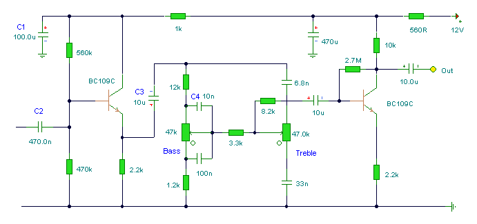
                Below (4th image) is a preamp with bass and treble shelving controls, also from Anderton. The tone controls use linear taper pots.

                What would happen if you had an EQ with a center detent, as on a graphic EQ, or with shelving filter pots, and you wanted it flat? If they were log taper the center detent would be in the wrong place on the taper. That's why they use linear taper.

                Here's another example, a basic Baxendall tone control circuit. You can find examples all over the place. Notice it says "Both tone controls should be linear potentiometers."

                Tone Control Circuit


                So where's the rest? All I see is a passive RC network.
                I was showing that part to show the dual ganged linear taper frequency controls.

                Nope, exponential taper.
                I'll let RG Keen answer this one:

                The Secret Life of Pots

                Which leads us to tapering.

                What is taper? It's just the ratio of the resistance already passed as the pot turns to the total resistance of the pot, described as a curve. For instance: we want to make a variable power supply with an adjustment pot that smoothly varies the voltage from one to ten volts, so we want a control that lets us do that. We have no idea whether we'll want mostly low voltages or high voltages, so we want to adjust it equally well anywhere in the range. In this case, it's most natural for the control pot to have an equal change in resistance or voltage divided per unit of rotation - we want the control to feel linear. This much of a turn is one volt, no matter whether it's near 0V or near 10V.


                Volume controls are different. The human ear does not respond linearly to loudness. It responds to the logarithm of loudness. That means that for a sound to seem twice as loud, it has to be almost ten times the actual change in air pressure. For us to have a control pot that seems to make a linear change in loudness per unit of rotation, the control must compensate for the human ear's oddity and supply ever-increasing amounts of signal per unit rotation. This compensating resistance taper is accurately called a "left hand logarithmic taper" but for historical reasons has been called an audio or log pot. In these pots, the wiper traverses resistance very slowly at first, then faster as the rotation increases. The actual curve looks exponential if you plot resistance or voltage division ratios per unit of rotation.

                No, I don't. A filter can't go down to 0Hz
                I was using 0Hz as an example. Filters certainly can go down to 0 Hz if they are passing DC.

                I would want the midway to be at 25Hz, not 53.0625Hz which would be the linear midpoint.
                Why? Unless it's just because you want to spend more time in the lower range, it serves no purpose. Like on a wah, you want something like an audio taper, also partly because you never get the full rotation. But the tone controls on mixers are linear. You want the same amount of boost or cut for the same amount of rotation.

                Do you want a smaller distance on the knob between the high frequencies than the low or vice versa? I don't.


                Sure I would. Because we don't hear frequency linearly. There's a big difference between 100Hz and 1.1KHz - that's a 1KHz difference - around 3 1/2 octaves. Wow! But there's hardly any difference between 10KHz and 11KHz, in terms of what our ear hears. The difference is less than one semitone. The difference from 10KHz to 20KHz is one octave. So yes, we want half the range to be crammed into just a small amount of the pot's rotation.
                You are talking loudness again. Set the Q on the filter to oscillate, and then turn the frequency control. You want an even sweep of frequencies from one end to the other. It doesn't matter if the low pitched stuff doesn't sound as loud. If you are trying to tune a filter to a pitch that would be very difficult to do with a non linear response.

                Just look at some commercial sweepable state variable filters. Every example I found uses a linear taper pot.

                You know why that pot is linear? Because the cutoff frequency is controlled by the clock generated by the NE555, and the clock rate of the NE555 is determined by the time constant of the resistor-capacitor circuit of which that pot is a part. The charging of the capacitor is exponential with respect to the timing resistor (our pot). So the response is still exponential.
                And here's some other examples below not using a clock.


                Again, where's the rest? I'd like to study it.
                Well I paid for that. You are welcome to buy a copy on the internet.

                So I think I've given enough real world examples that most commonly the frequency control on state variable filters, parametric EQs, as well as the level control on shelving filters, is linear. Are they all wrong?

                The bottom line is taper is a personal preference. You can't say you HAVE to have this or that taper, just what feels good to you.
                Last edited by David Schwab; 01-14-2010, 04:22 PM.
                It would be possible to describe everything scientifically, but it would make no sense; it would be without meaning, as if you described a Beethoven symphony as a variation of wave pressure. — Albert Einstein


                http://coneyislandguitars.com
                www.soundcloud.com/davidravenmoon

                Comment


                • #68
                  Pot comparisons

                  I found this really nice pot comparison video and chart.

                  YouTube - Guitar Potentiometers part 2, Comparing Linear/Audio Taper and Selecting Pots

                  Comment


                  • #69
                    Originally posted by David Schwab View Post
                    So how are you getting the voltage into the Tele?

                    The first image below is an Alembic LP filter. That would fit just fine. And that's a dual gang linear taper pot there. Yeah, other filter types take up a little more room, but not much. You just need a few more op amps and a way to switch between filter outputs.
                    I'll be using phantom power. I think I can do everything with a standard TRS 1/4" jack, but otherwise I can fit a DIN socket into the output jack cavity without routing, although I'm not sure how to mount it.

                    I'm sure the alembic filter is good, but I'm really into modularity. I think a 4-pole ladder filter sounds fantastic and if I make my guitar CV-compatible then I can use the ladder filter for other things when I'm not playing guitar, and as I said I could use the CV from the guitar to control other modules. But we're getting off-topic, if this interests you look out for another thread about this in the next couple weeks.


                    I'm relaxed, but you are telling me that all the filters I have used, both built by me and commercial units are wrong. I have also built voltage controlled synths back in the day.

                    Yep, still have the Matrix. I forgot they are VCFs, I though they were DCFs.
                    Okay, it's just that synthesizers are my primary area of expertise and I know that isn't so. I sold off all my analog synths so currently I have no physical device to demonstrate this. I could whip up a virtual instrument pretty quickly to demonstrate a virtual "potentiometer" controlling the cutoff of a lowpass filter under linear and exponential control, and let you decide which is best.

                    I believe the matrix 6 uses a CEM3396 for virtually all of the analog voicing, and naturally the exponentiator circuit is inside this IC: (see block diagram.

                    That whole argument is becoming a dead end because it's so much better to use an exponentiator (or something else to shape the response) than to approximate a curve with a pot that in active electronics linear pots are usually an obvious choice. Linear pots are fairly linear, but all of the other curves are merely rough approximations.

                    The state variable filter I used was not my design, it was Craig Anderton's. It didn't need any "work". In fact it's a fairly standard filter design, pretty much the same one used by Alembic, Wal, and others. See the next two pictures.

                    Anderton has several filter designs, and all use linear taper pots for frequency control. Every circuit I have for a state variable filter uses linear taper pots for frequency. See the pictures below.
                    I'm fairly familiar with that topology. Isn't it a little more like a parametric EQ? I also think the center frequency control is not over a wide range, so linear pots are usable (and certainly a lot more common/less expensive).


                    You missed the point. As you turn the frequency knob on a filter, you are sweeping the center frequency, not turning the level up and down as with a shelving filter or volume control. So you don't need a log taper because you are not dealing with volume changes. And guess what? Shelving filters use linear taper pots!
                    I never said anything about shelving. I don't think we are communicating clearly, and we might be grossly misinterpreting what we're saying to each other, causing frustration. That's my guess, because you're a smart, well-respected guy, and I'm also confident in my knowledge.

                    Let's look at a simple, very generalized graph of a lowpass filter. I'm sure this is very familiar to you, but it'll help us get on the same page.


                    So, if you put into this filter a sine wave of frequency and amplitude "1" (according to their scale), you get a sine wave of frequency "1" and amplitude ~".707". If the input frequency is "10", the output amplitude is ".1". If the frequency is ".1", the amplitude is very close to "1". This is very basic stuff. So a lowpass filter does not remove any frequency, it attenuates it.

                    What I am saying is that shifting the cutoff frequency (not controlling the amplitude of anything) effectively controls what frequencies are attenuated and to what degree. Basic stuff, right?

                    That's level, not pitch. Yes I know about the equal-loudness (Fletcher–Munson) contour, and that the ear is most sensitive to frequencies between 1 and 5 kHz. But that still has nothing to do with distributing a frequency sweep on a knob. That has to do with what sounds louder. If the frequencies from 1 and 5 kHz are somewhere on the middle of a pot, or at the clockwise end, it doesn't change how loud they sound, just where they are on he knob, and how soon you get to them. And that has more to do with the range of the filter.
                    No, nothing to do with frequency sweep. That was in reference to the graphic EQ, where it is understood that we are not controlling any of the parallel bandpass filters' center frequencies. A tangential discussion.


                    So that you have an even change in level. Otherwise a lot of the range would be squeezed together at the top end. You see this on fader on some mixing consoles. In that application it's appropriate, you want an even sounding fade. I have to assume the people designing this stuff know what they are doing.
                    Right, but is a graphic EQ not basically a mixer where each channel has the same input signal fed through a bandpass frequency set independently per channel? That's why it's curious to me.

                    Below (4th image) is a preamp with bass and treble shelving controls, also from Anderton. The tone controls use linear taper pots.

                    What would happen if you had an EQ with a center detent, as on a graphic EQ, or with shelving filter pots, and you wanted it flat? If they were log taper the center detent would be in the wrong place on the taper. That's why they use linear taper.
                    Actually, that does help explain it. The linear taper of a graphic EQs faders has nothing to do with our perception of how it will sound when swept, but is related to the physical operation and layout.

                    Here's another example, a basic Baxendall tone control circuit. You can find examples all over the place. Notice it says "Both tone controls should be linear potentiometers."

                    Tone Control Circuit


                    I was showing that part to show the dual ganged linear taper frequency controls.
                    But none of these control cutoff (or center) frequency over a wide range, so they are irrelevant.


                    I'll let RG Keen answer this one:

                    The Secret Life of Pots

                    Cool. It looks like R.G. agrees with me then. I agree with everything he says. Where is the contradiction?


                    I was using 0Hz as an example. Filters certainly can go down to 0 Hz if they are passing DC.
                    Sure, a filter can pass DC. I mean a filter with a cutoff/center frequency of 0Hz. It's not possible. you could get close, perhaps a well-designed filter could get down to small fractions of a Hz, at which point for audio we would cease to care. But it's not possible and it's also inconvenient to explain the octal frequency response with a lower frequency bound of exactly 0Hz, because what's twice, four times, eight times zero? 0Hz isn't really a frequency at all, because there is no periodicity.


                    Why? Unless it's just because you want to spend more time in the lower range, it serves no purpose. Like on a wah, you want something like an audio taper, also partly because you never get the full rotation. But the tone controls on mixers are linear. You want the same amount of boost or cut for the same amount of rotation.


                    Do you want a smaller distance on the knob between the high frequencies than the low or vice versa? I don't.
                    No. Let's use some more practical values. So we have our filter, and let's say we can push it to self-oscillation. The tunable range of the filter is from 110Hz (A2) to 1760Hz (A6). We would like the center of our self-oscillating filter to be at the center pitch. What is the pitch exactly in the center of A2 and A6? I would say A4 is exactly in the middle. A4 is 440Hz, but the linear midpoint is at 935Hz. Of course, some people would call 440Hz A3, but in that case we would define the range of the filter as A1 to A5, and everything else numerically remains the same.


                    You are talking loudness again. Set the Q on the filter to oscillate, and then turn the frequency control. You want an even sweep of frequencies from one end to the other. It doesn't matter if the low pitched stuff doesn't sound as loud. If you are trying to tune a filter to a pitch that would be very difficult to do with a non linear response.
                    Dave. Please read that again. I am clearly not talking loudness. I use the words "frequency", "octave", etc. multiple times and at no point do I discuss amplitude. I'm talking pitch. Frequency domain.

                    Just look at some commercial sweepable state variable filters. Every example I found uses a linear taper pot.


                    And here's some other examples below not using a clock.
                    I don't think any of those control a filter's cutoff frequency over a wide range (several octaves).


                    Well I paid for that. You are welcome to buy a copy on the internet.

                    So I think I've given enough real world examples that most commonly the frequency control on state variable filters, parametric EQs, as well as the level control on shelving filters, is linear. Are they all wrong?

                    The bottom line is taper is a personal preference. You can't say you HAVE to have this or that taper, just what feels good to you.
                    I can agree that there are applications where the most obvious taper isn't the most suitable one, and that there is some subjectivity. I just don't agree that frequency control is a situation that warrants a linear taper (whether that taper is generated by the pot or electronically).

                    Comment


                    • #70
                      Billy thanks again. I took your advice, and went looking for PEC Pots. It so happens they're in Toronto, (I'm not too far from there) so maybe I'll try and order them directly.

                      Is there a direct replacement PEC pot that you know of in place of a CTS? I called Tubes and More, they said the PEC's are NOT the same size as the standard CTS 500k solid short/shaft pots. What can you suggest?

                      Again, thanks for the info on resistors and such.

                      Comment


                      • #71
                        Unfortunately if you need a split knurled shaft pot you can get them from Allessandro or antique radio supply. They are expensive. They will fit into smaller cavities like a Tele and you can solder to the back. Otherwise, the PEC's are a larger body , solid shaft and the back is hard to solder too, (stainless). You don't really need to solder to the back , it is just convenient. and $7.95 ea. Should fit most hollow body and les paul or strat style guitars.

                        I believe you were talking about a Gretsch jet firebird. make sure you have about 2" diameter opening to work with around each pot. The pots measure 1.5 inches in diameter I believe. So 2" is tight but doable. And a knob that has a set screw, as I know vintage Gretsch's do.

                        The PEC pots are 3/8: opening and 1/4" shaft diameter, same as CTS. Only the body is larger diameter.

                        Comment


                        • #72
                          I'm sorry but the example posted : Tone Control Circuit , a poor example in an beginner made page, is *not* a Baxandall type tone control (which is active), but a poorly designed passive James tone control.
                          And in the passive type, the pots are not linear, but 10% logarithmic, to evenly balance losses in the high pass and low pass halves, and provide flat response on "5", (on a 0-10 scale), which is the reguar use.
                          The real Baxandall one is:
                          , which can be found at: Op-Amps as amplifiers and Tone Controls.
                          For those who want the real thing:http://www.dself.dsl.pipex.com/ampin...y/ampartew.htm
                          the *original* article by Peter Baxandall in Wireless World Magazine:
                          1952
                          Negative-Feedback Tone-Control Peter J Baxandall Oct 1952 p402
                          ;
                          a side comment on this article says:
                          1950-59
                          Baxandall, P J "Negative-Feedback Tone-Control" Article published Wireless World Oct 1952, p402.
                          This is the famous article that introduced the Baxandall tone-control, which was for decades the universal choice in preamplifiers and mixing consoles, and is still by far the most popular arrangement where people feel they can permit themselves tone-controls at all.
                          Before this article, tone-controls could be incredibly complicated, often involving switches and inductors. See Chapter 15 of The Radio Designer's Handbook by Langford-Smith; the currently reprinted 4th edition came out in 1953, but rather surprisingly does not mention the Baxandall concept; perhaps it appeared too close to the publication date.
                          Apart from the payment for the article (which would not have been generous in 1952) I think I am right in saying that Peter got no financial return from this, his most famous idea.
                          As an example of a properly-designed James tone control, just check the typical Ampeg tone controls, with its properly dimensioned 10:1 (20dB) attenuation appearing everywhere: treble capacitors: 4n7/47nF ; Bass capacitors: 10n/100nF; Bass resistors: 220K/22K; 10% Log Pots: 1M Log or Audio.
                          This gives uniform attenuation (20dB) across the audio band (flat response), with pots set on "5", less attenuation (perceived as "boost") on higher values and the corresponding symmetrical "attenuation" on lower values.
                          On the contrary, on the real Baxandall negative feedback tone controls, linear pots are used so there's symmetry on both halves of treble and bass networks, achieving flat response on "5".
                          Mind you, linear pots are not the best choice, because then tone boost and cut is not uniform to our ears, but the required "S" curve one is complicated to make and very expensive.
                          Common feedback type graphic equalizers also would need "S" pots, which is economically out of the question.
                          Another reference to the original one, and by no less an authority than J. Linsley Hood:
                          http://books.google.com/books?id=rn8...0valve&f=false
                          Last edited by J M Fahey; 01-14-2010, 09:03 PM. Reason: Forgot Link
                          Juan Manuel Fahey

                          Comment


                          • #73
                            BillyZ.... you said
                            The best I have found are PEC available at Antique Radio supply. But others like the custom CTS pots from RS guitars and others.
                            I called PEC - they're in Toronto, not far from me. Someone there helped me locate 2 options for pots...

                            MIL Style RV4
                            http://www.precisionelectronics.com/...tyle%20RV4.pdf - which he said was VERY close to the 500K solid CTS pots I have.

                            and

                            MIL Style RV2:
                            http://www.precisionelectronics.com/...tyle%20RV2.pdf

                            I'd like to know, what pots from them have you used? What model etc? Here's their page: Product Specs

                            Much thanks again.

                            Comment


                            • #74
                              Originally posted by maltone View Post
                              BillyZ.... you said

                              I called PEC - they're in Toronto, not far from me. Someone there helped me locate 2 options for pots...

                              MIL Style RV4
                              http://www.precisionelectronics.com/...tyle%20RV4.pdf - which he said was VERY close to the 500K solid CTS pots I have.

                              and

                              MIL Style RV2:
                              http://www.precisionelectronics.com/...tyle%20RV2.pdf

                              I'd like to know, what pots from them have you used? What model etc? Here's their page: Product Specs

                              Much thanks again.
                              It seems this thread has broken into two separate discussions, ha ha.
                              No problem for me, I find the other discussion interesting and far more technical.

                              Well, I think I learned something. RV2 is a 1 watt rated pot and RV4 is a 2 Watt pot. And the RV2 is a Brass body meaning you can solder to it.

                              The RV2 looks like exactly what you ( and I ) want. Most of mine are KA series or RV4 . KA is the commercial number, I understand it is the same pot.

                              The RV2 looks like a 3/4 diameter opposed to the RV4 which is 1" diameter.

                              By the way you can also order from Digikey.

                              I would go with the RV2 500k A . let us know how it turns out.

                              I have compared PEC to CTS , Alpha , Bourns an others. The PEC is only bested by some vintage Centralab Pots, equal to Clarostat A/B.

                              Comment


                              • #75
                                BillyZ, thanks again.

                                You said:
                                The RV2 looks like a 3/4 diameter opposed to the RV4 which is 1" diameter. I would go with the RV2 500k A . let us know how it turns out.

                                I have compared PEC to CTS , Alpha , Bourns an others. The PEC is only bested by some vintage Centralab Pots, equal to Clarostat A/B.
                                I'm trying to get pots that are the same size, body etc as my current CTS Pots. Really, those centralabs are hard to find, and very expensive. Ideally, I'd like to find a drop in replacement that's rated not only 500K or above for ALL pots (matched), but also pots with a taper of 70:30 or 65:35 (preferred).

                                Billy, can these PEC pots be used "as is", or do they need to be tweaked somehow to be used as audio log pots?

                                If I call PEC back, would it be correct to ask them, "what's the taper ratio of these pots"? - Thanks again Billy.

                                Comment

                                Working...
                                X