Announcement

Collapse
No announcement yet.

Dual Output

Collapse
X
 
  • Filter
  • Time
  • Show
Clear All
new posts

  • Dual Output

    So I've been thinking lately about some really interesting wirings for and old SX bass I've got lying around. I've got a concept I'm really excited about but I'm not sure how to apply it. I was wondering if anyone could give me clues as to how to wire it up so that multiple pickups can go to mulitple outputs.

    In other words, three pups that can be switched on or off on two different outputs. I can't think of a way to allow the same pickup to go to two outputs without combing the two into one circuit and making the outputs identical, which is exactly what I do NOT want - identical outputs.
  • #2
    I had a stereo Vox Phantom 12-string once, and it had three pickups with each half (under 3 pairs of strings) which could go to the left or right output.

    It had 3 way switches for each pickup which was off in the center, and then on left or on right. It used Strat type lever switches, but you can do it with mini toggle switches.

    So get a SPDT (or DPDT if they are easier to find) center off toggle switch for each pickup. You wire the pickup to the center lug, and each output to the other two.
    It would be possible to describe everything scientifically, but it would make no sense; it would be without meaning, as if you described a Beethoven symphony as a variation of wave pressure. — Albert Einstein


    http://coneyislandguitars.com
    www.soundcloud.com/davidravenmoon

    Comment


    • #3
      I toyed with a similar idea for my old Performer P/J bass that I wished to convert to an M1/P/J (M1 being the DiMarzio Model one or something akin to that) with stereo outputs.

      Originally posted by Stealth
      Here goes another crazy idea.

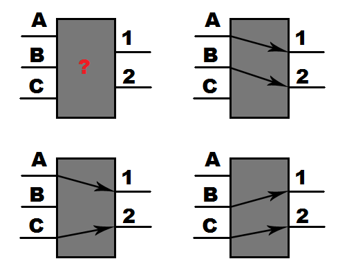
      Suppose you had a triple-pickup bass, let's say a P/J with an extra Model One stuck in the neck position. Let's label the Model One A, the P-pickup B, and the J-pickup C.

      Now, suppose that you wish to avoid pickup loading and have only two pickups active at the same time - that is, either AB, BC or AC, and that you've got a VOL/TONE stack after each of the outputs.

      To put it in a picture: A, B, C are pickups, 1, 2 are outputs towards the V/T stacks.


      Would it be possible to find a switch that'd let me have the following options:

      1) A -> 1, B -> 2
      2) A -> 1, C -> 2
      3) B -> 1, C -> 2

      What goes on after the V/T stacks is irrelevant at the moment - potentially, a mono/stereo pair of jacks, but right now it's not that big of an issue.

      What do I need? What kind of <something>P<something>T switch would do this kind of trick? A rotary, maybe?
      Originally posted by tubby.twins
      To original poster: here is how to do this with a rotary switch.

      At minimum, you will need a rotary switch with 2 poles and 3 positions. Here is a comparable rotary switch by Alpha Taiwan (sold by Mouser) which I have used in some similar wiring projects:
      http://www.mouser.com/Search/Product...46eK00OIdVA%3d

      (This switch actually has 4 poles; you may ignore two of them for this purpose.)

      Pins: (refer to the datasheet)
      This switch has 4 center lugs, one for each pole. Each pole is switchable between one of three outer lugs. The outer lugs are labeled 1-12; the corresponding pole lugs are labeled A, B, C and D.

      Wiring:
      Connect the positive lead from pickup "A" to outer lugs 1 and 2.
      Connect the positive lead from pickup "B" to outer lugs 3 and 4.
      Connect the positive lead from pickup "C" to outer lugs 5 and 6.
      Connect output "1" to center lug A.
      Connect output "2" to center lug B.
      Do not use center lugs C or D, or outer lugs 7-12.

      Operation:

      When the rotary switch is turned to the first position (counter clockwise) center lug A will be connected to outer lug 1. This will send pickup "A" to output "1". At the same time, center lug B will be connected to outer lug 4. This will send pickup "B" to output "2".

      When the rotary switch is turned to the center position, center lug A will be connected to outer lug 2. This will send pickup "A" to output "1". At the same time, center lug B will be connected to outer lug 5. This will send pickup "C" to output "2".

      When the rotary switch is turned to the last position (clockwise) center lug A will be connected to outer lug 3. This will send pickup "B" to output "1". At the same time, center lug B will be connected to outer lug 6. This will send pickup "C" to output "2".

      Hope this helps! I have always preferred using rotary switches instead of sliders (or a series of toggles) for these kinds of switching tasks. The result looks cleaner, IMO.
      Last edited by Stealth; 09-29-2009, 08:51 AM.
      Pickup prototype checklist: [x] FR4 [x] Cu AWG 42 [x] Neo magnets [x] Willpower [ ] Time - Winding suspended due to exams.

      Originally posted by David Schwab
      Then you have neos... which is a fuzzy bunny wrapped in barbed wire.

      Comment


      • #4
        Later on, while considering the many possible wirings I've read about, I recalled an old discussion going about Rickenbacker replacement pickups. Of all the manufacturers who made those (and there aren't many), Bartolini had a little extra - a micro-pickup that fit inside the muting foam compartment inside the bridge, and it was commonly wired in parallel with the neck pickup. So, following that little idea, I once again deferred to tubby.twins for extra ideas:

        Originally posted by Stealth
        Hey, tubby.twins,

        first of all, thank you for the exhaustive wiring info. I'm still trying to sort it out and figure out how to do it, but I think I'll get it right the moment I get my hands on that exact switch.

        How many more switching combinations could go on that switch? One other combination I've hit upon that would probably be useful involves all three pickups, similar to how Bartolini-modified Rickenbackers were wired: (neck and cavity pickup parallel on one output, bridge pickup on the other output). Going by the same schematic (http://img.photobucket.com/albums/v2...ss/wiringj.gif), would it be possible to add the following:
        • A + C -> 1
        • B -> 2


        to the same switch (Alpha 4-pole, 3-pos, make-before-break) you suggested? Something tells me I'd need a fourth position on the switch as well.

        Thank you in advance and pardon the nagging; electronics really isn't my forte and I'm still trying to figure it out how it all works.

        -- Stealth
        Originally posted by tubby.twins
        Hi Stealth!

        It's no problem at all. I enjoy playing with rotary switches and exploring the options that are available.

        You are correct, you would need a 4-position rotary switch to get the other configuration that you wanted. However, you would also need another pole, in order to prevent both pickups A and C from always being tied together. The new pole would connect pickup C to output 1 only in that one position where both A+C are sent to output 1.

        Assume you have a 3-pole 4-position rotary switch, with poles labeled A, B and C; and lugs labeled 1-12. Pole A switches between lugs 1-4, pole B switches between lugs 5-8, and pole C switches between lugs 9-12.

        Pickup A is going to connect to lugs 1, 2, and 3.
        Pickup B is going to connect to lugs 4, 5, and 6.
        Pickup C is going to connect to lugs 7, 8, and 9.
        Lugs 10, 11, and 12 have no connection.

        Output 1 connects to poles A and C.
        Output 2 connects to pole B.

        Walking through all the positions of the rotary switch:

        Position 1:
        Pole A connects lug 1 (pickup A) to output 1.
        Pole B connects lug 5 (pickup B) to output 2.
        Pole C connects lug 9 (pickup C) to output 1.
        Result: pickups A and C (in parallel) to output 1; pickup B to output 2.

        Position 2:
        Pole A connects lug 2 (pickup A) to output 1.
        Pole B connects lug 6 (pickup B) to output 2.
        Pole C connects lug 10 (no connection) to output 1. This has no effect.
        Result: pickup A to output 1; pickup B to output 2.

        Position 3:
        Pole A connects lug 3 (pickup A) to output 1.
        Pole B connects lug 7 (pickup C) to output 2.
        Pole C connects lug 11 (no connection) to output 1. This has no effect.
        Result: pickup A to output 1; pickup C to output 2.

        Position 4:
        Pole A connects lug 4 (pickup B) to output 1.
        Pole B connects lug 8 (pickup C) to output 2.
        Pole C connects lug 12 (no connection) to output 1. This has no effect.
        Result: pickup B to output 1; pickup C to output 2.

        This would get you all 3 of the combinations you asked for originally, plus the new "Bart-Rick" combination.

        I hope this helps! Please feel free to ask more questions.

        Regards,
        - tubby.twins
        Hope this helps. Right now I'm still in the process of learning how to wind my own pickups (and the M1 is nigh-impossible to find at a decent price) so my three-pickup design is still on ice. I hope you'll make something of this idea and let me know how it turns out.
        Pickup prototype checklist: [x] FR4 [x] Cu AWG 42 [x] Neo magnets [x] Willpower [ ] Time - Winding suspended due to exams.

        Originally posted by David Schwab
        Then you have neos... which is a fuzzy bunny wrapped in barbed wire.

        Comment


        • #5
          Originally those Bart Hi-A mute pickups worked like a regular pickup. Then they made them so they just added to the neck pickup.

          I borrowed that idea and put a single coil pickup in the mute compartment, and had it wired like a regular pickup. It was some bobbin from an old Teisco or something. Then I added a Dimarzio Model P between the neck and bridge pickups. I also changed the toaster for an old Carvin humbucker. I had a lot of switches on that bass!

          I had a Hi-A pickup in my '74 Rick at the bridge. I got that back in 1977. It was one of the first humbuckers he made. The older models had one coil per string.

          It would be possible to describe everything scientifically, but it would make no sense; it would be without meaning, as if you described a Beethoven symphony as a variation of wave pressure. — Albert Einstein


          http://coneyislandguitars.com
          www.soundcloud.com/davidravenmoon

          Comment


          • #6
            David - that's pickup's grand-son (the Bart 6JH) is what originally set me off thinking the fourth position (the MM||J -> 1, P -> 2) would be worth the experiment. The exact thing you describe (the Hi-A mute compartment pick-up being complimentary to the neck 6RT) is what drove me to look for the final solution.

            I seem to recall you yourself posting in the exact original thread, asking why I wouldn't include all the pickups in the setup. Considering the original idea (that it'd be a stereo output system) - I hope this answers that question asked long ago. Otherwise, truth be told, I'm not sure if I'd get that much tonal diversity from doing a MM -> 1, P||J ->2 combination or, say, the third combination, MM||P ->1, J -> 2 - it seems to me like the MM||J parallel would be a way to go.

            Of course - at this point I'm just talking out of my hindquarters, as I haven't verified the wiring myself - but I figure it might work by some odd sense.
            Pickup prototype checklist: [x] FR4 [x] Cu AWG 42 [x] Neo magnets [x] Willpower [ ] Time - Winding suspended due to exams.

            Originally posted by David Schwab
            Then you have neos... which is a fuzzy bunny wrapped in barbed wire.

            Comment


            • #7
              I remember thinking the Rick's stereo outputs would be cool, and at one point ran each pickup to a 10 band EQ. But eventually I wired the bass up as mono, mostly because I added two more pickups and things like varitones. It was far more useful to have all the pickups feed into a single preamp.

              But it was cool to stick the Brassmaster on the bridge pickup and an EH Mole on the neck.

              Lately I'm thinking I'd like to have active tone controls for each pickup before I blend them together.

              Currently all my working basses are passive while I do some restoration on my main bass, and as I'm building my prototypes for a preamp.

              I haven't played a passive bass in years, but it's not that bad.

              Tubby's wiring ideas are pretty interesting. On his latest bass, I expected the "virtual" positions between pickups to be a little more distinct, but I also told him I though mixing two pickups together has some cool tones, which is the way he's doing it now.

              It looked very cool seeing three of my pickups on his bass.
              It would be possible to describe everything scientifically, but it would make no sense; it would be without meaning, as if you described a Beethoven symphony as a variation of wave pressure. — Albert Einstein


              http://coneyislandguitars.com
              www.soundcloud.com/davidravenmoon

              Comment


              • #8
                Originally posted by David Schwab View Post
                It looked very cool seeing three of my pickups on his bass.
                There was *almost* enough room for a 4th pickup right next to the bridge, but I didn't want to push my luck.

                And yes, the new switching scheme is proving to be very nice. I'm really enjoying the new blended tones.

                Comment


                • #9
                  Originally posted by tubby.twins View Post
                  There was *almost* enough room for a 4th pickup right next to the bridge, but I didn't want to push my luck.

                  And yes, the new switching scheme is proving to be very nice. I'm really enjoying the new blended tones.
                  Great!

                  I'm working on that new/old bridge pickup... I'm going to try some new ideas.
                  It would be possible to describe everything scientifically, but it would make no sense; it would be without meaning, as if you described a Beethoven symphony as a variation of wave pressure. — Albert Einstein


                  http://coneyislandguitars.com
                  www.soundcloud.com/davidravenmoon

                  Comment


                  • #10
                    Hey, tubby.twins, glad to see you here as well.
                    As I said, the three-pickup idea is on ice for the time being - however, the quad-coil-MM switching schematic you provided me with might soon come to fruition, as the warranty on my six-string with the humbucker just expired two days ago. I still have the original PDF you sent me and I've given it a thorough read, now the entire switching system makes sense.
                    Pickup prototype checklist: [x] FR4 [x] Cu AWG 42 [x] Neo magnets [x] Willpower [ ] Time - Winding suspended due to exams.

                    Originally posted by David Schwab
                    Then you have neos... which is a fuzzy bunny wrapped in barbed wire.

                    Comment

                    Working...
                    X