Ad Widget

Collapse

Announcement

Collapse
No announcement yet.

How Bad Is It To Have A 100k Volume Pot?

Collapse
X
 
  • Filter
  • Time
  • Show
Clear All
new posts

  • How Bad Is It To Have A 100k Volume Pot?

    I'm building a travel guitar for my son, basically a single pickup Steinberger style headless, but I'm embedding a headphone amp. I've wired up a 4pdt switch so when you turn on the pocket amp it switches the volume pot from external amp mode to internal amp mode. The trouble lies in the fact that the pocket amp wants it's original 100k volume pot and is unhappy with the 500k audio pot I've tried, it's range is all in the 1st 30 deg or so. I tried putting a 100k resistor in parallel with the pot, which should make it ~83k, but it curiously seems to have no affect whatsoever.

    So do I just use the 100k, lose brightness when it's plugged into a real amp, and it is what it is? Or is 100k simply too low? No one expects it to to be the best sounding guitar ever, I'm not a guitarist and this is my 1st build of one. I scavenged the neck and hardware off a pawn shop Epiphone SG and made my own design tuner tailpiece. The odd thing about it was the volume pots were linear and the tone audio! Did some Malaysian worker have an off day or was that deliberate?

    Any ideas on how to reconcile the 2 systems would be appreciated, it seems the amp pot is doing more than simple voltage dividing, and that's where my understanding of these things peters out.
  • #2
    Try the audio taper 'tone' 500k pot as the vol control.
    But if the 100k vol pot sounds ok, then it's ok; it might lose a little brightness but if it's bright enough then so what. Pete.
    My band:- http://www.youtube.com/user/RedwingBand

    Comment


    • #3
      Originally posted by pdf64 View Post
      Try the audio taper 'tone' 500k pot as the vol control.
      But if the 100k vol pot sounds ok, then it's ok; it might lose a little brightness but if it's bright enough then so what. Pete.
      That is the pot I used. I'm thinking the reason the parallel resistor didn't work is it basically changes an audio taper 500k to a linear 83k.

      Comment


      • #4
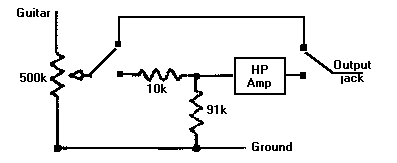
        Why don't you stick a voltage divider at the front of the headphone amp, that only gets switched in when the amp is selected. So, let's say a voltage divider comprised of a 10k fixed resistor and a 91k fixed resistor to ground, with the input signal to the amp coming from the junction of the 10k/91k. As far as the amp's concerned it IS looking at a 100k (101k, but after tolerances are factored in, who's counting?) pot, turned down just a bit. That there is a 500k pot just ahead of that one matters little to the amp.

        Comment


        • #5
          Mark, I'm not sure I follow the "in front" part. I've run 3 wires from where the 100k volume control pot was mounted on the PC board to the 500k, through a 4PDT switch to the 500k. And doesn't that plan render the 500k useless?

          Comment


          • #6
            Does't need to be that complicated.

            Imagine the headphone amp was in a little stompbox chassis, with a switch that either connected your guitar to it, or completely bypassed the headphone amp and fed the guitar to the output jack directly.

            Okay, not imagine the headphone amp had a 100k input-level pot. If you plugged your guitar into it, you'd be taking the output off a 500k guitar pot, and feeding it to a 100k input-level pot on the amp, right? In effect, you'd have two "steps" of signal attenuation before the signal hits the actual headphone amp chip.

            Since you don't really need two separate contiguous volume pots, make one of them a "fake" pot, using two fixed resistors. This slapped-together diagram shows exactly what I'm taking about. The 10k/91k pair is part of the headphone amp and the DPDT switch bypass them and the amp so that your "normal" guitar volume pot goes right to the output jack...as it should. Make sense?

            Comment

            Working...
            X