Announcement

Collapse
No announcement yet.

Need tech info on older Japanese pickup

Collapse
X
 
  • Filter
  • Time
  • Show
Clear All
new posts

  • Need tech info on older Japanese pickup

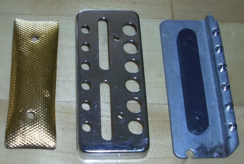
    I'm trying to rebuild this one from the 60's. Anybody have any idea what it is, and what goes in it? I'm assuming it is a Silvertone or Harmony or similar, but can't find anything similar on-line. The plastic bobbin is shot, so I'm using some ultrathin PCB material glued to the top and bottom of the magnet to form the bobbin. Got my choice of wires to work from, so I just need to know what ind and how much.

  • #2
    After a bit more poking around, it seems like the pickup is clearly a Teisco/Norma "gold foil" of some type. I haven't yet seen any pics of something identical, but the pictures I have seen are obviously the same machining, but the 3 punches used to make the cover are simply shuffled around. See this Teisco pic.

    Comment


    • #3
      That also looks like some variety of Teisco to me. They definitely moved the punches around. I have several old Teisco's laying around. Here are three versions. Only one of mine has the gold foil, the other two have black tolex looking material instead.

      I measured 5.55k, 4.96H on the first, 5.05k, 4.16H on the second, and 6.36k, 6.21H on the third. I did take the bobbin out of the second one and wire looks to be 42poly it measured .0025 inch od. The bobbin looks like nylon and it is glued to the magnet like you are proposing. Looks like they put some kind of sealer around the edges to protect the wire (where paper tape would be in a HB bobbin). It looks like glue.


      Last edited by SonnyW; 07-12-2010, 05:14 AM. Reason: not sure why the pics aren't showing up.
      www.sonnywalton.com
      How many guitars do you need? Just one more.

      Comment


      • #4
        Originally posted by Mark Hammer View Post
        After a bit more poking around, it seems like the pickup is clearly a Teisco/Norma "gold foil" of some type. I haven't yet seen any pics of something identical, but the pictures I have seen are obviously the same machining, but the 3 punches used to make the cover are simply shuffled around. See this Teisco pic.
        It's a Teisco , the Norma style has the central pole screws . I have numerous guitars with both types , sonically two totally different pickups , the Teisco being the hotter & less microphonic.

        Last edited by bramley; 07-12-2010, 01:24 PM.

        Comment


        • #5
          The design of this Teisco is similar to that of the old Epiphone "New Yorker" pickups, in that it is a single coil that is cosmetically like a HB.

          You can see in the picture I posted at the start of the thread that the "adjustable pole pieces" are simply an extension of the pole on the bottom of the magnet, such that the sensing zone is between that row of pole pieces and the top of the bar magnet. (with, one assumes, some additional sensing area between the other edge of the magnetically conductive bottom plate and the top of the magnet. In view of the location of the sensing area, small wonder that it is a fairly hot pickup for the number of turns. I gather the additional iron, in the form of the bottom plate, has some role in the inductance?

          Thanks for the followup, fellas. Much appreciated.

          Comment


          • #6
            This may help. These days anything with six holes and gold foil is labelled " Ry Cooder" but this is the genuine Coodercaster unit.


            and the rear of the " less desirable " Norma, they use some kind of magnetized rubber.

            Last edited by bramley; 07-12-2010, 01:42 PM.

            Comment


            • #7
              Folks -

              This thread has put an idea in my head. It seems that as a group we're in a very good position to create some sort of sticky "Catalog of Commercialized Magnet-Coil-Polepiece-Fluxguide Arrangements," perhaps including subjective comments from owners of iconic examples. There really is an interesting world beyond the usual architectures of Strat-Humbucker-P90...

              Comment


              • #8
                Agreed. Good idea.

                Bramley,

                Can't see the pics at work, but looking forward to seeing them later tonight at home. If it's this one - RyCooderGears - then I guess I'm on the right track.

                Comment


                • #9
                  Originally posted by bramley View Post
                  This may help. These days anything with six holes and gold foil is labelled " Ry Cooder" but this is the genuine Coodercaster unit.

                  Do you know what the reading was? It's impossible to read in that photo.


                  and the rear of the " less desirable " Norma, they use some kind of magnetized rubber.

                  It's a rubber ceramic magnet, similar to the things you stick on your fridge. Rickenbacker and Lace use them too.
                  It would be possible to describe everything scientifically, but it would make no sense; it would be without meaning, as if you described a Beethoven symphony as a variation of wave pressure. — Albert Einstein


                  http://coneyislandguitars.com
                  www.soundcloud.com/davidravenmoon

                  Comment


                  • #10
                    Mark,

                    Those inductance readings I posted earlier were way off.. I took them with a Tenma LCR which was all I had at the time. But today, by chance my new Extech 380193 meter came in the UPS. So I decided to test those old pickups again. Wow- I had no idea the frequency would matter that much. From what I can gather here on the forum 1khz is what most folks are using. Assuming I am operating the meter right (haven't had a chance to study the manual) I got:

                    1799 mH on the first, 1501 mH on the second and 2.363 H on the third. that is letting the meter autorange. The readings did change a little if I selected the range manually. Anyhow that's half of what I posted earlier so I was blown away. Since the inductance was so far off, I rechecked the DCR readings using the multimeter on my Tek 2236 oscilloscope. They did change a little but I think that was mostly just due to the temperature. By the way the third one did have an extra metal cover over the baseplate so I think the amount of metal does influence it.

                    Anyway I didn't want to leave the wrong info uncorrected. Wish I had one of the coodercaster ones to measure -- or a bunch of them --

                    Bramley,

                    I like those old 60's and 70's Teiscos, Normas, and Kent/Silvertone/Kawai etc guitars a lot too. I collected a few of them over the years. I have one that is definitely a Norma, one that is definitely a Teisco, and three that could be any of the names they used because the logos have come off. I like them all. They are what they are, but some of them when set up well are pretty nice. I have one that is good for slide and I keep it out all the time. (now if I could only play slide - oh well) A couple have really nice acoustic tone and I had thought that someday I might try rewinding some pickups to help them out when plugged in. The one you posted is really nice - not sure if it is a Spectrum or Audition or what but it looks like a keeper.
                    www.sonnywalton.com
                    How many guitars do you need? Just one more.

                    Comment


                    • #11
                      Originally posted by David Schwab View Post
                      Do you know what the reading was? It's impossible to read in that photo.


                      It's a rubber ceramic magnet, similar to the things you stick on your fridge. Rickenbacker and Lace use them too.

                      Yes, sorry bout the pic quality. Average reading was 6.15 K across six pickups.

                      Comment


                      • #12
                        Originally posted by SonnyW View Post
                        Those inductance readings I posted earlier were way off.. I took them with a Tenma LCR which was all I had at the time. But today, by chance my new Extech 380193 meter came in the UPS. So I decided to test those old pickups again. Wow- I had no idea the frequency would matter that much. From what I can gather here on the forum 1khz is what most folks are using. Assuming I am operating the meter right (haven't had a chance to study the manual) I got: ...
                        I looked at the Tenma LCR datasheet. They make no mention of the allowed range of Q, which generally means that low Q inductors (such as guitar pickups) are not correctly measured. This isn't just due to frequency, and is a problem with most handheld LCR meters. The Extech is one of the few exceptions.

                        You are right that 1 KHz is the standard test frequency for audio components, although sometimes the 100 Hz data is interesting as well, although 100 Hz is really intended for testing power transformers and the like.

                        What is this "Q"? It is the ratio of the inductive (or capacitive) reactance to the AC resistance.

                        For example, an ideal 1 Henry inductor in series with a 7,000 ohm resistor has the following reactances: 6,283 ohms at 1 KHz, and 628.3 at 100 Hz. The AC resistance in both cases is 7 Kohm, so the Q values are 6,283/7000= 0.898 and 0.0898 respectively. Yes, the Q varies with test frequency. This is another reason to test audio components at 1 KHz.

                        And what is "AC resistance"? It is the DC resistance (what an ohmmeter measures) plus eddy current and core losses, if any. The Extech measures AC resistance only. In our example, the inductor is ideal, so no eddy current and core losses, and the AC resistance is just the DC resistance of that resistor.

                        Comment


                        • #13
                          Given the obligatory shallowness of the coil (the bottom plate, magnet and cover don't permit much depth), I'm going to go with #43, since I doubt I'd be able to reach 6.1k in that space using #42. There is just not enough room for the requsite number of turns. I have some #44, too, but my luck beyond #43 is not especially good.

                          Comment


                          • #14
                            Thanks Joe, for the explanation, these really help. I was an EE major in college for the first three years then changed to Industrial, so this is not all greek to me, but that was 40 years ago so I am really rusty on my theory these days. I need to dig out my old textbooks and brush up some. I did get some time to go through the instructions that came with the Extech but it wasn't all that helpful. Your explanation spells it out much more clearly to me. Of course I realize it is only scratching the surface. Every time I start to get a handle on one piece of the puzzle it brings up another factor or nuance I hadn't considered.

                            I knew the Tenma meter wasn't the best for this, which is why I ordered the Extech. But I failed to realize just how significant the differences would be, and I didn't know about the Q factor problem with the handheld meters at all. It still blows me away that it was off by a factor of 2. This really points out how significant the eddy current and core losses are. They are a lot higher percent than I would have guessed, or taken the other way around the Q is a lot lower than I imagined. Now that I have the Extech I can take these factors into account.

                            Should I be using the parallel (PAL) mode to measure pickup inductance? I think that's what I used in the numbers I posted because the instructions said it was for high impedances. But high isn't really defined and I could use a little clarification on that. I'm assuming passive pickups would be high and active would be low. It does change the readings.

                            This is all very helpful to me. After a lot of agonizing, I broke down and got a CNC winder about 6 weeks ago and finally got it going. I am now going through the process of trying to understand how tension and turns per layer etc. affect the coil properties. I have made half a dozen humbuckers with the new machine so far and switched out magnets and rewound a couple of them several times. None of them sounded as good as the handwound few I made before I got the machine. So far not even close. Actually they didn't sound good to me at all. I wouldn't buy them myself and I sure don't want to sell them with my name on them. At least with some theory and numbers to go on I won't be burning through so much good plain enamel wire learning. I haven't tried single coils on it yet. I have been speeding up my pickup making efforts lately because I have a year or so to go before I can retire from my day job. I am not selling any yet, but would like to be making humbuckers I can be proud of by then.
                            www.sonnywalton.com
                            How many guitars do you need? Just one more.

                            Comment


                            • #15
                              Originally posted by SonnyW View Post
                              Thanks Joe, for the explanation, these really help. I was an EE major in college for the first three years then changed to Industrial, so this is not all greek to me, but that was 40 years ago so I am really rusty on my theory these days. I need to dig out my old textbooks and brush up some. I did get some time to go through the instructions that came with the Extech but it wasn't all that helpful. Your explanation spells it out much more clearly to me. Of course I realize it is only scratching the surface. Every time I start to get a handle on one piece of the puzzle it brings up another factor or nuance I hadn't considered.
                              You know, it's a slippery slope...

                              But if you search the forum for my name, you will find many tutorials written as the need arose over the years

                              I knew the Tenma meter wasn't the best for this, which is why I ordered the Extech. But I failed to realize just how significant the differences would be, and I didn't know about the Q factor problem with the handheld meters at all. It still blows me away that it was off by a factor of 2. This really points out how significant the eddy current and core losses are. They are a lot higher percent than I would have guessed, or taken the other way around the Q is a lot lower than I imagined. Now that I have the Extech I can take these factors into account.
                              A good test is to put one winding of an audio transformer in series with a 50 K pot, the other windings being open-circuited, and measure the inductance of the series string with a LCR meter. See how the indicated inductance varies as the pot is adjusted.

                              Handheld meters (costing ~ $200) use a single test frequency at a time, and do not use data from more than one frequency for calculation of parameters. Many fancier lab LCR meters (costing thousands) measure at multiple frequencies, and use the variation of complex impedance with frequency to choose the lumped-parameter circuit model that best matches the measured data.

                              Should I be using the parallel (PAL) mode to measure pickup inductance? I think that's what I used in the numbers I posted because the instructions said it was for high impedances. But high isn't really defined and I could use a little clarification on that. I'm assuming passive pickups would be high and active would be low. It does change the readings.
                              For pickups, the SER setting is more useful.

                              But be aware of how such LCR meters work: The fundamental measurement is that of complex impedance at the chosen test frequency. When one selects L, C, or R, and then selects PAR or SER, the measurement does not change. What changes is the math used to go from that complex impedance to parameter values.

                              This is all very helpful to me. After a lot of agonizing, I broke down and got a CNC winder about 6 weeks ago and finally got it going. I am now going through the process of trying to understand how tension and turns per layer etc. affect the coil properties. I have made half a dozen humbuckers with the new machine so far and switched out magnets and rewound a couple of them several times. None of them sounded as good as the handwound few I made before I got the machine. So far not even close. Actually they didn't sound good to me at all. I wouldn't buy them myself and I sure don't want to sell them with my name on them. At least with some theory and numbers to go on I won't be burning through so much good plain enamel wire learning. I haven't tried single coils on it yet. I have been speeding up my pickup making efforts lately because I have a year or so to go before I can retire from my day job. I am not selling any yet, but would like to be making humbuckers I can be proud of by then.
                              It will take at least that year to figure things out. There is a lot of art in the pickup maker's art. Not to mention artifice.

                              Comment

                              Working...
                              X