Announcement

Collapse
No announcement yet.

Low Impedance Pickups: What Am I Doing Wrong?!

Collapse
X
 
  • Filter
  • Time
  • Show
Clear All
new posts

  • Low Impedance Pickups: What Am I Doing Wrong?!

    Hi all, I wanted some low impedance pickups to go with the prototype guitar I recently finished, but I am having a heck of a time getting them to work. Here are some vital specs for what I am trying to accomplish:

    - 1/8" thick aluminum frame
    - CSE187 transformer (also have a cheapo 2000:1 transformer from the bay)
    - Ceramic bar magnet pulled from cheapo strat pickup (just to try the idea out)
    - 470k burden resistor from output signal to output ground to mimic a 500k volume pot

    I have tried wiring the transformer up with the frame on either side of the transformer, with and without the load resistor. I have tried both transformers that I have, I have tried using neodymium disc magnets instead of the ceramic, orienting each of the four long faces of the magnet "up", all to no avail. Here is a picture of one of the arrangements I tried. I used brass strip to connect the transformer to the coil in an attempt to avoid the higher resistance of lead wire. To test, I have held the arrangement over the strings of one of my guitars and strummed with the pickup plugged in to a clean amp. I'm at my wits' end, as this doesn't seem like it should be too difficult. What am I missing?

    Click image for larger version

Name:	DSCN0597.JPG
Views:	1
Size:	1.41 MB
ID:	870444

  • #2
    I've never experimented with single-loop low-Z pickups, but understand they require very small resistance across any connections.
    I suspect the aluminum-to-copper interface may be an issue.

    https://en.wikipedia.org/wiki/Aluminium_oxide


    Al2O3 is an electrical insulator but has a relatively high thermal conductivity(30 Wm−1K−1) for a ceramic material....

    Aluminium oxide is responsible for the resistance of metallic aluminium to weathering. Metallic aluminium is very reactive with atmospheric oxygen, and a thin passivation layer of aluminium oxide (4 nm thickness) forms on any exposed aluminium surface. This layer protects the metal from further oxidation.
    I presume the real experts will be arriving shortly.

    Good luck,
    rjb

    PS: Nice handiwork.
    Last edited by rjb; 03-31-2016, 03:33 PM. Reason: style
    DON'T FEED THE TROLLS!

    Comment


    • #3
      Hey Ripthorn,

      The real experts will show up soon, but basically you have two issues:

      1. Looks like your transformer is backwards. The extremely heavy wires coming out of the CSE187 are the primary and should be connected to your aluminum pickup loop by the lowest resistance connection you can get. You will probably be OK for a trial setup with the screws and nuts and copper you have, but make a very good soldered connection to the primary wires with your copper sheet/tape. You are dealing with extremely low resistances here so make darn sure everything is extremely clean and tight in that primary loop.

      2. 470K load resistor isn't necessary and is the wrong value anyway.

      Note: The secondary wires of the CSE187 may be connected to your output jack. But you have to be aware that the output of this pickup will be at microphone level, not guitar pickup level. You can't go into a guitar amp with this, you need a mic preamp such as found on most mixers, or a standalone mic preamp. Make sure phantom power is off on the mic preamp.

      Comment


      • #4
        Regarding point 1: I tried the transformer both ways and it didn't work either way. However, for the connections, the current design doesn't lend itself well to a direct connection with the transformer primaries. I wonder how Lace does it?

        2. Good input. I have a mic pre I can use before going into the amp. I'll see if I have any luck. Any idea how much gain I might need?

        Comment


        • #5
          Originally posted by Ripthorn View Post
          Hi all, I wanted some low impedance pickups to go with the prototype guitar I recently finished, but I am having a heck of a time getting them to work. Here are some vital specs for what I am trying to accomplish:

          - 1/8" thick aluminum frame
          - CSE187 transformer (also have a cheapo 2000:1 transformer from the bay)
          - Ceramic bar magnet pulled from cheapo strat pickup (just to try the idea out)
          - 470k burden resistor from output signal to output ground to mimic a 500k volume pot

          I have tried wiring the transformer up with the frame on either side of the transformer, with and without the load resistor. I have tried both transformers that I have, I have tried using neodymium disc magnets instead of the ceramic, orienting each of the four long faces of the magnet "up", all to no avail. Here is a picture of one of the arrangements I tried. I used brass strip to connect the transformer to the coil in an attempt to avoid the higher resistance of lead wire. To test, I have held the arrangement over the strings of one of my guitars and strummed with the pickup plugged in to a clean amp. I'm at my wits' end, as this doesn't seem like it should be too difficult. What am I missing?
          [ATTACH=CONFIG]38432[/ATTACH]
          The CSE187L is only a 500 turn current transformer (CT) and has an output impedance near 200 ohms or that of an XLR microphone input level of about 3 to 5 millivolts when terminated on the primary side with a very low string loop resistance in the range of about 800 micro-ohms total including the 250 micro-ohms of the installed U shaped single turn on the current transformer of 250 micro ohms. By wiring it to a 500K pot, you are assuming that this has an output similar to a 6000 to 8000 turn high impedance pickup which this is not. Try wiring it to a microphone input with the CT output going to pins 2 and 3 of the XLR and pin 1 going to ground (wire pin 1 to the string loop and the frame of the CT) and let us know if it sounds better? As an alternative you can use a Shure A95U type mic matching transformer with about a 1 to 12 step up turns ratio.

          Rjb made a good comment about keeping the string loop resistance very low as this low resistance allows the primary loop current to be higher when the resistance is lower. Try using copper in place of the aluminum and solder it directly to the CT primary by drilling a tight matching hole in the copper plate. Use silver solder for lower resistance.

          For those who are not familiar with current transformer guitar pickups here is the key fact: A low resistance string loop coupled to the CT primary is critical to having a workable low impedance mic level output.

          Here is how to calculate the output impedance of the CT using 500 turns on the secondary such as the CSE187L. Square the CT secondary turns or 500 squared to be 250,000. That is one quarter of a million. Then, look up the resistance of the primary string loop wire gauge or copper plate resistance in microohms per length used in your design. Example; if AWG11 is 105 microohms per inch then a 5 inch hairpin loop will be 525 microohms. Divide 525 by 4 to get 131.25 ohms at the output added to the impedance of the 250 microohms transformer loop within the transformer frame being 80 ohms. I measured this by bending the CT primary together and soldering it and measuring the CT output impedance with an Extech LCR meter and getting 80 ohms. Add 131.25 to 80 and the output impedance of this AWG 11 5" string loop is 211.25 ohms or just right for an XLR microphone input impedance. Knowing these calculation procedures means you do not need an Extech LCR meter but only calculate the CT output impedance by looking up the resistance of the primary string loop.

          I applaud your courage in trying this very different pickup design. Try using a copper sheet instead of aluminum, making a very low resistance string loop, and let us know how it turns out?

          Post any other questions.

          Joseph J. Rogowski

          Comment


          • #6
            Ripthorn,

            It's possible that you were using a guitar amp for your testing and never could hear the output because the gain was too low, or one of the times you had it connected right, there was too much loop resistance on the primary and the output was even lower than it should be.

            Almost any mic preamp will have an adjustable gain range from about 20 to 50-60 dB and assuming you have a good low resistance loop, you should be fine with that range.

            Joe Rogowski replied to your thread and he is absolutely "the man" on the ultra low Z pickups; you can see his long-running topic thread here on the forum.

            One possible tip is that you might be able to use hobby shop thin copper tubing to attach the primary wires to the screws/bolts on your aluminum loop. One size of copper tubing will slip fit over the wires and you can use the plumbing brazing trick (when it's hot it will suck solder into the slip joint.) On the other end you can improvise or flatten the tube or solder it to a piece of flat sheet copper. Use silver solder and keep the connecting tubes/wires as short as possible. It might be to your advantage to go to a copper loop.

            Lace actually makes the transformer as an open core coil and I think they just slip it over part of the Alumitone frame then finish bending to the final shape, although I could be wrong on that. To finish the loop they may actually tack weld the aluminum frame at one point. Maybe someone else on the forum could comment on that.

            Comment


            • #7
              Originally posted by charrich56 View Post
              Ripthorn,

              It's possible that you were using a guitar amp for your testing and never could hear the output because the gain was too low, or one of the times you had it connected right, there was too much loop resistance on the primary and the output was even lower than it should be.

              Almost any mic preamp will have an adjustable gain range from about 20 to 50-60 dB and assuming you have a good low resistance loop, you should be fine with that range.

              Joe Rogowski replied to your thread and he is absolutely "the man" on the ultra low Z pickups; you can see his long-running topic thread here on the forum.

              One possible tip is that you might be able to use hobby shop thin copper tubing to attach the primary wires to the screws/bolts on your aluminum loop. One size of copper tubing will slip fit over the wires and you can use the plumbing brazing trick (when it's hot it will suck solder into the slip joint.) On the other end you can improvise or flatten the tube or solder it to a piece of flat sheet copper. Use silver solder and keep the connecting tubes/wires as short as possible. It might be to your advantage to go to a copper loop.

              Lace actually makes the transformer as an open core coil and I think they just slip it over part of the Alumitone frame then finish bending to the final shape, although I could be wrong on that. To finish the loop they may actually tack weld the aluminum frame at one point. Maybe someone else on the forum could comment on that.
              charrich56,

              The reason why Lace uses an aluminum frame is because it is stamped out and light and remains a continuous string loop or two. In order to transfer the current in the string loop, Lace uses interlaced C-shaped transformer laminations through the aluminum frame in just the right place where the two low impedance aluminum loops would be connected in series. This maintains the low resistance of the string loop as the aluminum frame is acting as a humbucker low impedance primary set of string loops with no need to be cut to be connected to an external transformer. Under the Alumitone pickup frame are two 10,000 (or more) turn coils wound on the laminated C shaped cores that are the secondary output. The key is to maintain a low resistance primary string loop impedance to be magnetically coupled to the secondary coils.

              Lower Resistance string loops, including all connection points, makes for a higher current primary circuit current and this makes for a higher output depending on the number of turns on the secondary. If you use about 300 to 750 turns on the CT secondary you are in the low impedance microphone range. If you use a CT with 5000 turns you will be in the higher impedance pickup range. You can design for what you can easily find. That is why I used the CSE187L as it matched a mic input well, has a metal frame that can be grounded and has a pretty thick AWG 12 installed primary. Search the web for CTs and try what you can find. Let your ears be the final judge.

              Welcome to the world of low impedance pickups.

              You seem to understand how they really work.

              Joseph J. Rogowski
              Last edited by bbsailor; 03-31-2016, 03:19 AM.

              Comment


              • #8
                What about piggybacking a second transformer onto the output of the first one to get impedance up to the guitar amp input range?

                Comment


                • #9
                  Originally posted by David King View Post
                  What about piggybacking a second transformer onto the output of the first one to get impedance up to the guitar amp input range?
                  Off hand, I'd say you'd be adding bulk to the guitar and losing the advantage of a low impedance balanced line.
                  Why not put the second transformer at the amp end?
                  DON'T FEED THE TROLLS!

                  Comment


                  • #10
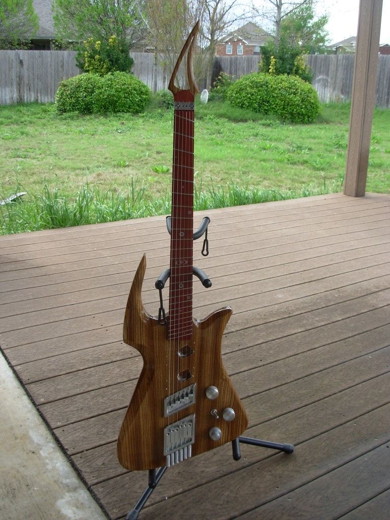
                    Thanks for all the comments, guys. Here is my thinking: I have enough space that I could run a copper loop under my aluminum frame and use the aluminum just as decoration. All the other hardware on the guitar is made by me out of aluminum, so the aluminum look needs to stay, but functionally speaking, I can get a loop of 10 or 12 AWG wire under there. I could then install mic matching transformers for each pickup in the control cavity (I have plenty of space there). Does that sound like a good plan? Just so that you can see what I'm working on, this is the guitar, which is my own design I call the Photon. It is about 1 1/4" thick, weighs about 6 lbs or so without pickups, and plays very smoothly.

                    Comment


                    • #11
                      Nice hardware! What about using solid silver wire for your sensing loop? Not sure what the conductivity of pure vs sterling is but pure silver won't tarnish as quickly. It's much easier to solder than aluminum too.

                      Comment


                      • #12
                        Originally posted by David King View Post
                        Nice hardware!
                        Agreed.
                        But watch out- you could put an eye out with that headstock!
                        DON'T FEED THE TROLLS!

                        Comment


                        • #13
                          Originally posted by Ripthorn View Post
                          Hi all, I wanted some low impedance pickups to go with the prototype guitar I recently finished, but I am having a heck of a time getting them to work. Here are some vital specs for what I am trying to accomplish:

                          - 1/8" thick aluminum frame
                          - CSE187 transformer (also have a cheapo 2000:1 transformer from the bay)
                          - Ceramic bar magnet pulled from cheapo strat pickup (just to try the idea out)
                          - 470k burden resistor from output signal to output ground to mimic a 500k volume pot

                          I have tried wiring the transformer up with the frame on either side of the transformer, with and without the load resistor. I have tried both transformers that I have, I have tried using neodymium disc magnets instead of the ceramic, orienting each of the four long faces of the magnet "up", all to no avail. Here is a picture of one of the arrangements I tried. I used brass strip to connect the transformer to the coil in an attempt to avoid the higher resistance of lead wire. To test, I have held the arrangement over the strings of one of my guitars and strummed with the pickup plugged in to a clean amp. I'm at my wits' end, as this doesn't seem like it should be too difficult. What am I missing?

                          [ATTACH=CONFIG]38432[/ATTACH]
                          I downloaded the attached photo and then I enlarged it to see the details of your connection. Charrich56 is right about the transformer being wired wrong. Your photo seems to show the low impedance primary thick turn wired to the output jack. It is wired wrong. The thick U shaped single turn is AWG12 wire is the input connection and that should somehow be connected to your aluminum string loop from underneath to fit the space in your guitar body. Since you seem pretty good at metal work, here is how you might want to proceed using the aluminum plate. Drill two holes spaced .375 inches apart to match the CSE187L primary wire spacing spanning the loop opening. Find a threaded metal machine screw that will accept solder. Drill the machine screw with a number drill that just matches the diameter of the heavy primary wire about .125" to .187" deep. Ensure that the holes line up so you can clean the aluminum plate (to ensure a good low resistance connection) and mount these two screws with a nut. Insert the current transformer primary wire in each screws hole and solder. Over time this connection may get worse so you may need to clean it again. The voltage generated in the output is directly related to the current being induced on the primary string loop including the series connection of the CT primary making one string loop that is measured in micro-ohms. Use the strongest magnet that is practical. K&J Magnetics has a line of neo magnets that are .125" thick, 2" long and .25" and .375" wide. You can even use ceramic magnets or individual round magnets. If the neo magnets have a metal coating make sure that you don't short out the string loop with the magnet coating.

                          Look on the web for the "Les Paul Recording guitar schematic". This LP Recording model guitar is wired for low impedance pickups similar to the impedance of the CSE187L output level and impedance. Do you have access to an oscilloscope or an Extech 380193 LCR meter?

                          Another possibility is to use the Prem Magnetics SPCT-251 which has 2000 turns and no primary installed. Just make your own a U shaped primary (like a miniature U bolt using .160" round metal stock) with threads on each end of the primary loop and screw it to the underside of the string loop plate. Call their engineer and ask if they can make you a special limited run using AWG 43 on the secondary with a full bobbin of about 6000 to 8000 turns or as many turns that will fit. This way your output will be in the high impedance zone and you can use traditional pickup volume and tone controls. You can see the physical size of this current transformer on their web site.

                          Keep us posted about your progress. This looks like a fun project. One benefit about your design is not needing large pickup holes in traditional places that could affect the energy conservation of the neck-body system on the string vibration energy.

                          Joseph J. Rogowski

                          Comment


                          • #14
                            Originally posted by bbsailor View Post
                            I downloaded the attached photo and then I enlarged it to see the details of your connection. Charrich56 is right about the transformer being wired wrong. Your photo seems to show the low impedance primary thick turn wired to the output jack. It is wired wrong. The thick U shaped single turn is AWG12 wire is the input connection and that should somehow be connected to your aluminum string loop from underneath to fit the space in your guitar body.
                            Yes, I know the connection is backwards. I too the picture after wiring it backwards because I had already tried it "correctly" and didn't have any "success". It sounds like my problem was correctly defining success . I can tuck a copper loop under the aluminum and wire the copper wire directly to the transformer, that shouldn't be an issue. I just like the aluminum for the look. I will likely go ceramic on the finished product. I have a couple DL-CT1005A transformers, that are 2000:1 that I also tried without any audible output from my amp set at normal bedroom playing levels. I will look into mic matching transformers so I can plug straight into an amp. I would probably go copper plate instead of wire if it wasn't expensive (this guitar has run my spending money completely out).

                            Comment


                            • #15
                              I cannot tell you why this does not work at all, but I can tell you why it will not be very efficient. In a magnetic pickup:

                              1. The magnet magnetizes the strings, mostly only right over the magnet.
                              2. It is the magnetic field from the string that counts, or actually how much it changes through the coil when the string vibrates. (Read something on Faraday's law of magnetic induction.)
                              3. The magnetic field lines from the string go down through the center of the coil and then loop around back up to the string.
                              4. Field lines going down contribute to one polarity of voltage; field lines going up to the other polarity.
                              5. Including lines going up and down through the coil results in some cancelation.

                              Your wide flat single turn conductor intercepts a significant amount of flux going back up as well what is coming down and so there is some cancellation. This is also complicated by the fact that your conductor is so wide that different parts of the strip enclose different amounts of flux, and a sort of averaging process takes place before you can sense the voltage. I think you are better off with a "single turn" that is roughly square in cross section located close to the magnet structure.

                              Another possibility is to use a material with significant permeability inside the "coil" with the magnet below. This material (probably a ferrite is best for this kind of pickup) guides the flux from the string, tending to contain it so that it loops around only after it has passed through the coil. In this case you could use a single turn conductor more like a strip wound around the permeable material, that is, having a small size in the direction of the strings, but larger in the direction away from the strings. This would be a different way to get the low resistance you need while keeping the conductor size small in the direction along the strings.

                              Originally posted by Ripthorn View Post
                              Hi all, I wanted some low impedance pickups to go with the prototype guitar I recently finished, but I am having a heck of a time getting them to work. Here are some vital specs for what I am trying to accomplish:

                              - 1/8" thick aluminum frame
                              - CSE187 transformer (also have a cheapo 2000:1 transformer from the bay)
                              - Ceramic bar magnet pulled from cheapo strat pickup (just to try the idea out)
                              - 470k burden resistor from output signal to output ground to mimic a 500k volume pot

                              I have tried wiring the transformer up with the frame on either side of the transformer, with and without the load resistor. I have tried both transformers that I have, I have tried using neodymium disc magnets instead of the ceramic, orienting each of the four long faces of the magnet "up", all to no avail. Here is a picture of one of the arrangements I tried. I used brass strip to connect the transformer to the coil in an attempt to avoid the higher resistance of lead wire. To test, I have held the arrangement over the strings of one of my guitars and strummed with the pickup plugged in to a clean amp. I'm at my wits' end, as this doesn't seem like it should be too difficult. What am I missing?

                              [ATTACH=CONFIG]38432[/ATTACH]

                              Comment

                              Working...
                              X