Ad Widget

Collapse

Announcement

Collapse
No announcement yet.

Internal transformer in Mono/Poly

Collapse
X
 
  • Filter
  • Time
  • Show
Clear All
new posts

  • Internal transformer in Mono/Poly

    Hi everybody, I'm new here !

    I'm trying to find out how to replace the internal transformer of a Korg Mono/Poly synth (it is now enabled for 110V and I would like to use it for 230V).

    I would prefer to use this solution instead of buying an external step down transformer...

    Any idea ?

    Thanks in advance for your time !
  • #2
    Does the transformer that's in it now have a single primary winding, or two primary windings? If it's got two, then they're likely in parallel now allowing the device to run on 110v. If you wire them in series you'll be able to run the device on 230v.

    Can you get a brand/model number off of the transformer that's in it now?
    -Mike

    Comment


    • #3
      Korg used two different transformers, one for 100/120v and another for 220/240v.

      But it is a simple power supply, the transformer has just one center tapped secondary. The schematic doesn't call out the voltages, but it creates the +/-15vDC rails. SO that means the raw supply would be in the 20-25vDC range. And that means the AC from that secondary would be in the 30-36vAC range, center tapped.

      The secondary leads are fused at 1.6A, and the whole unit is rated to draw 28 watts from the wall.

      You should have no trouble finding a plain old commercial power transformer of similar specs.
      Education is what you're left with after you have forgotten what you have learned.

      Comment


      • #4
        thank you Enzo and Defaced,

        I am trying to compare the schematics with the actual boards but this is a bit tricky to me..

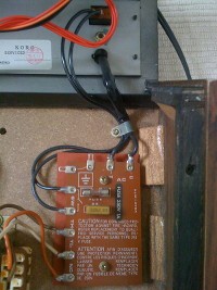
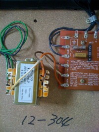
        Defaced, here are pictures that I thought would be helpful


        Enzo, if I correctly understood you, I should look for a transformer that is 30-36vAC range, center tapped ?

        again, thanks

        Comment


        • #5
          Yes, that was my suggestion. However, the existing 120v transformer works properly doesn;t it? If so, apply 120VAC to its primary and measure the secondary voltages. That way there should be no confusion.

          Looking at your photos, doesn;t the transformer label state right on it "39V" and "33.5VA?" 39v is not far off from my suggestion, and 33.5VA (volt-amps) is for your purposes the same as 33.5 watts.

          The two green wires would be the 39v and the blue one the center tap. The schematic should be clear as to how those three wires connect. Is it not clear to you?

          Also your label says "100v." Is this unit from Japan? They run on 100v instead of 120, so applying 120 to it might raise the secondary more than desired.


          Oh, and welcome to the forum, by the way.
          Education is what you're left with after you have forgotten what you have learned.

          Comment


          • #6
            Thank you for your welcoming message Enzo!
            I don't know if the 120V work as I am still waiting to receive an external step down transformer to power it on and verify all is fine with it;
            but you are right, the unit is from Japan.
            And for the schematics, I'll be honest with you: they prove a bit difficult to u
            decifer...

            Comment


            • #7
              Do you have a variac? Dial it down to 100v and connect the unit to it.

              Where is your difficulty with the schematics? Power supplies are pretty much the same wherever they are. I am looking at the power supply schematic on board KLM376. The transformer is lower left by the power switch. the secondary center tap is shown connected to ground, and the secondary leads are each fused on their way to the bridge rectifier.
              Education is what you're left with after you have forgotten what you have learned.

              Comment

              Working...
              X