Ad Widget

Collapse

Announcement

Collapse
No announcement yet.

organ leslie for guitar

Collapse
X
 
  • Filter
  • Time
  • Show
Clear All
new posts

  • #31
    I've been reading up on "back-EMF" and studying the methods of protection. It looks to me that the capacitors and resistors (labeled A,B,C,D) between relay 1 and the motors are the back-EMF protection. In that case, since relay 1 is between relay 2 and the motors, does relay 2 need protection as well?

    I also read quite a bit about the need for protection from back-EMF on the control side of the relays. This would, in my case, be protecting my stomp switches from the back-EMF produced by the relay coils. This was the reason that I originally drew a diode across the control side of relay 2. I suppose if I were going to do that, I'd want a diode at relay 1 as well.

    Also, I've learned an interesting thing about wall warts, just because it's labeled 9V, doesn't mean that's what you'll get:

    Zoom ac adapter- stated:9V 300mA measured: 13.07V
    R.Shack ac adapter- stated 9V 150mA measured: 15.09V

    The output voltage of each drops when under load, but never comes close to 9V in my device. I'm not really sure how to deal with this. Maybe I should look for a lower rated transformer and see if it comes closer to an actual 9V?
    Comment


    • #32
      I learned about back EMF years ago when I tried to copy the older Leslie brake circuit for one of my single-speed Leslies. The circuit works by applying DC to the motor windings for a time determined by an Amperite thermal delay tube.

      The original used selenium rectifiers, but I tried to copy it with silicon diodes. The diodes failed instantly despite my replacing them with higher current versions. Apparently, selenium rectifiers have enough internal resistance to damp the current surge. Silicon diodes do not.

      I did eventually get the brake circuit working, but didn't like the results. On the single-speed Leslies, the lower rotor takes a while to spin down; on the two-speed Leslies, the slow motor applies some braking.

      What you've found with transformers is that they are voltage rated at a certain current. With an AC-AC wall wart, you should always find a higher voltage with no load. Under load, losses in the windings and iron will cause the voltage to drop. Don't confuse them with DC regulated supplies--and even many DC wall warts are unregulated.

      Comment


      • #33
        First of all, fan speed controls and lamp dimmers are not the same. The fan controller has some extra circuitry to deal with inductive loads. I've tried using regular lamp dimmers to control motors, and they just explode.

        The dimmers sold for use with low-voltage halogen lighting will work with motors, though.

        Next, and I guess this is the point Rhodesplyr is making, induction motors don't like being controlled by varying the voltage. You can get away with it in a fan application, because the torque demand from a fan (and the airflow too) falls off very steeply as you lower the speed. So you don't need much of a control range, and it doesn't matter if the motor runs inefficiently at lower settings.

        Spinning a Leslie baffle, though, it may not work so well. You want a wide speed range, and the torque needed at low speeds may still be pretty substantial, if the load is friction rather than air.
        "Enzo, I see that you replied parasitic oscillations. Is that a hypothesis? Or is that your amazing metal band I should check out?"

        Comment


        • #34
          I'm always kinda bummed when people don't report back as to whether the suggestions they got were helpful or not, or what the eventual outcome was. I always think that it would be potentially helpful for the next guy. (I'm new here though, so correct me if I'm wrong.)

          So, to wrap up my part of this thread, I was eventually successful (after countless hours spent on something that would probably take most of you guys 20 min.). I learned a lot.

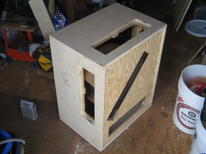
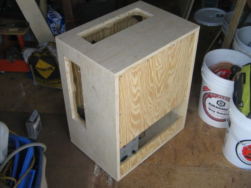
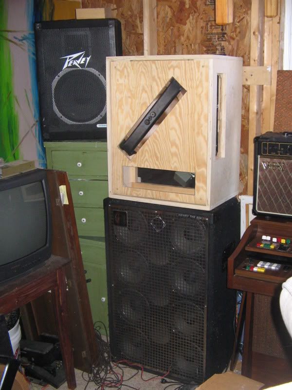
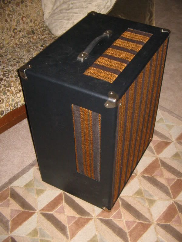
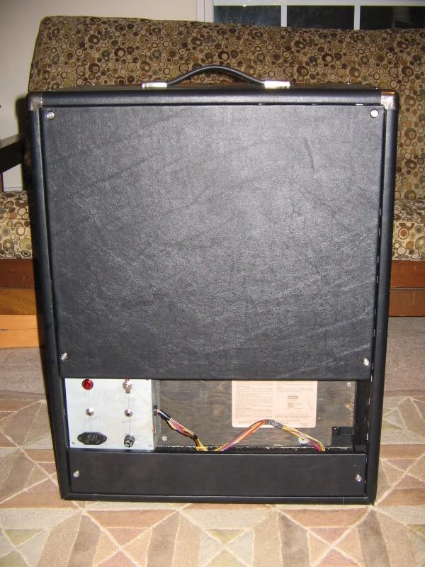
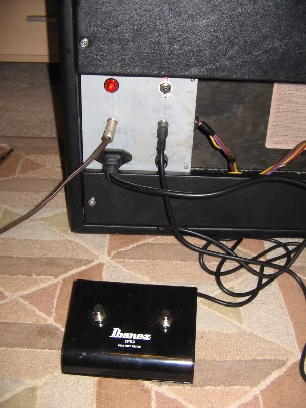
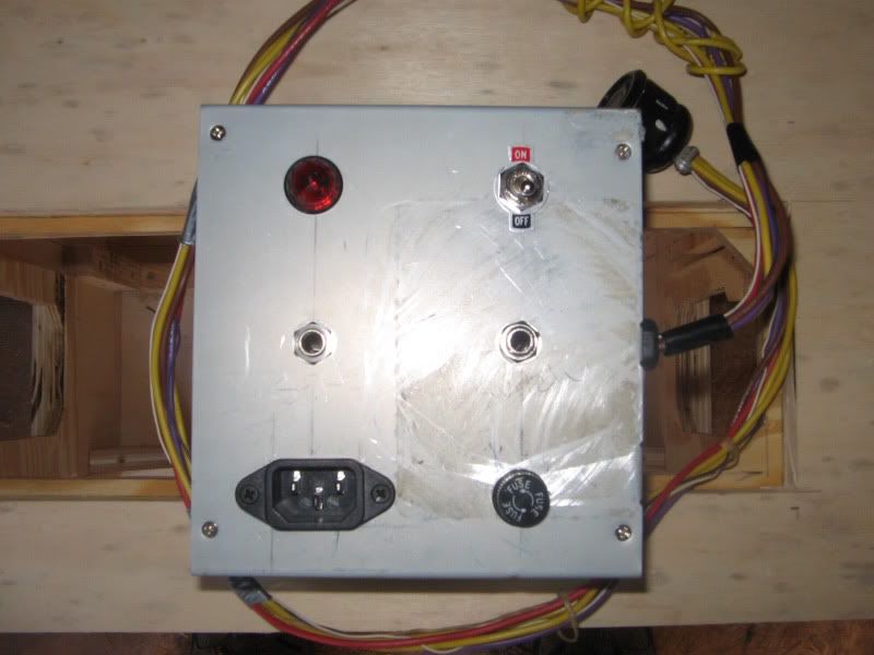
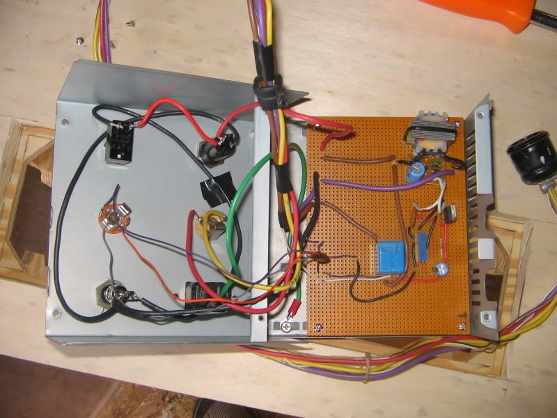
          I built a controller interface that allows me to plug my amp and a two button low voltage footswitch into the cabinet. The two switches are on/off and fast/slow. I also plugged it into a single speed Leslie unit that I have and it works on it too. The foot switches just act as two on/offs. So when I build it's controller, I can leave out one relay and one switch.

          I'll attach some photos and my schematic. It was my first attempt at using TinyCad. I know it's a mess, but I think it's pretty accurate.

          The cabinet still needs to be sanded, routed, tolexed, the grill cloth applied, and the control box painted, but it works and sounds great. The finish work will have to wait because the pickups just came in for the two lap steels I'm building and my wife is starting to complain about the two amplifiers I have in pieces in the dining room.

          Thanks for the input.


          I used a salvaged pc power supply for my box. Perfect size, cool stuff inside too.

          Rat's nest.

          Front


          Back


          Here it is, on top of a Henry the 8x8 for size comparison, almost as big, almost as heavy.
          Attached Files
          Last edited by spsimmons; 02-20-2010, 05:00 AM. Reason: oops

          Comment


          • #35
            allen organ speaker for guitar

            howdy all i got this allen organ speaker that i want to use for guitar, how can i know what things i need to buy to make this work ?
            Attached Files

            Comment


            • #36
              Originally posted by Alf View Post
              A revolving speaker ? Very interesting !

              How did you accomplish this ? How do you apply the power to the speaker, gliding contacts ?
              The classic Leslies like the 122 and 147 use a stationary speaker firing into a rotating baffle or horn, but some (not the one under discussion here) actually used a small speaker mounted in a rotor that got its voice coil connections via a "Mercotac"--a device that used mercury. They are apparently still made in some form:

              Slip Rings

              Organ players have been running 120VAC through their switches for years for 147 type Leslies, but I guess that scares guitar players ;-)

              Comment


              • #37
                re: allen speaker

                Need more info. What about a model number and/or some pictures of what's inside. Nice looking cabinet.

                Comment


                • #38
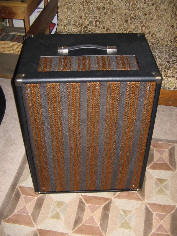
                  I forgot to post my finished photos.


                  Comment


                  • #39
                    id forget about all the other rotating speakers besides leslies.... you wont be happy... for guitar get a 145 or 147... same amp... short or tall cab... motor stacks run on b+ voltage from organ or must be supplied via preamp pedal or facsimile... go to hamtech.org.... these questions have been answered a million times

                    frank Uboat

                    Comment

                    Working...
                    X