Announcement

Collapse
No announcement yet.

how do you make a bass rolloff pad for a condenser mic?

Collapse
X
 
  • Filter
  • Time
  • Show
Clear All
new posts

  • #16
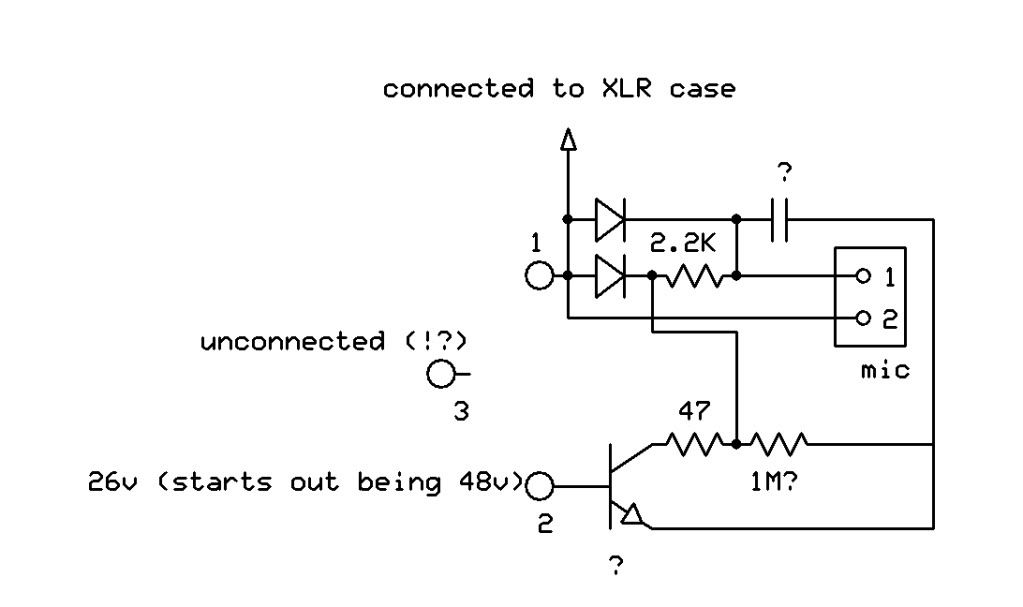
    the TO92 thingie seems to be regulating, but I doubt it's a 78xx type, probably it's just a general purpose transistor, receiving +26 V on its collector, base held at 7V, around 6V appear at the emitter.
    It *might* have a series resistor, dropping +48 to +26 and easing the transistor dissipation.
    That resistor which "eats" 22V out of 48, may be too much for a 17V supply.
    OK, enough guessing, let's see what the cat brings.
    Juan Manuel Fahey

    Comment


    • #17
      Here's the schem:


      Kind of annoying that pin 3 is unconnected - they could've at least impedance balanced it. I'm unsure of the type of transistor shown here, or even if it's connected this way (since I don't know the pinout). It does seem likely that it's acting as a regulator though. The 1M resistor I'm unsure of because the writing is so small it's hard to see.

      Any ideas on how to set this up for 15v?

      Thanks

      Comment


      • #18
        Another interesting development:

        I connected the mic to the mixer that has 16v for it's phantom supply, and there's still roughly 6v at the mic. Maybe 6.3 instead of 6.7, but could that be enough to cause it to distort on loud chords when using the 16v supply? I suppose there's going to be a line that is crossed where the supply voltage is too low, but it seems pretty close here.

        Comment


        • #19
          Dear Tempus.
          I'm very sorry but that schematic does not make sense.
          If you post a couple sharp well illuminated pictures from each side of the board we *might* trace it.
          Phantom power should get to pins 2 and 3. Does it?
          Juan Manuel Fahey

          Comment


          • #20
            It doesn't make a lot of sense to me either, but I'll post some photos. As for pin 3, it's not connected to anything. Using a meter with 1 probe on it and 1 on any other node shows an open.

            I guess they never said it had a balanced out, and it appears it doesn't.

            Thanks

            Comment


            • #21
              I think you should dust your soldering iron and build the *real* balanced mic in that link above.
              You don't even "need" an enclosure, just stick the small board inside your guitar with some foam double sided tape, until happy with results. Good luck.
              Juan Manuel Fahey

              Comment


              • #22
                Ya I may end up just doing that. In the meantime, I may try this mod and see how it works:


                I'd remove the transistor, connect pin 2 directly to the 47 ohm resistor, drop a 2.2K resistor from pin 3 to ground to balance it, and drop a 2.2k resistor to ground at the mic to form a voltage divider bringing the 16v down to 8, which the mic should be OK with.

                I may need to do a little more calculating to get a better value for the pin 3 resistor, but I think it might work.

                Comment


                • #23
                  Dear Tempus, maybe you can build this into your Bullet, even using some parts already there.

                  This is very simple, will work for sure, is *not* balanced (the original isn't either), gets power from pin 3 and injects audio in pin 2, the unwritten but generally accepted convention.
                  I forgot: will work from 16V.
                  C2 is the "bass cut" capacitor, pay attention to its polarity, the voltage on Pin 2 is higher than what the capsule receives.
                  Play with its value until finding what you want.
                  Good luck.
                  PD: any more complex than this, you're better building the posted "real balanced" one.
                  Juan Manuel Fahey

                  Comment

                  Working...
                  X