Ad Widget

Collapse

Announcement

Collapse
No announcement yet.

Instrument headphone amp

Collapse
X
 
  • Filter
  • Time
  • Show
Clear All
new posts

  • Instrument headphone amp

    I'm looking for some simple ideas for a battery powered, intrument level to headphone amp. It's sole purpose will be for tuning my pedal steel in noisy bars so loud and clean is best. I've seen a few super simple circuits for line level inputs such as this one http://tangentsoft.net/audio/cmoy-tu...angent-sch.pdf It says you could jack up the gain for a guitar level input (Maybe another pot in series with the feedback resistor?) albeit with much worse noise. I don't really care about noise for this function but if there's a better way to do this while keeping it relatively simple that'd be nice.

    And now to contradict my request for simple, I wonder if it would be advisable to have some sort of limiting or compression as I could see the transients of the steel really farting out the headphones when at an otherwise good level.
  • #2
    The simplest thing is to use either a dedicated headphone/low-power amp chip like an LM-386 ( LM386 - Low Voltage Audio Power Amplifier ) or any of the op-amps like the NE5532 or LM833 that are comfortable driving low-impedance loads. Here is an illustration of one in action: http://www.paia.com/prodimages/hdasch.pdf

    Entering "LM386 headphone amp" or "NE5532 headphone amp" will get you to plenty of useful and usable schematics. Note that the NE5532 is a dual op-amp which ends up getting used for stereo applications. For stage-tuning purposes, you don't really need stereo, but you probably do need both ears occluded by headphones. You can do that via a stereo arrangement (that would let you use normal MP3 player headphones/earbuds) or you can run them in mono and simply parallel the two NE5532 sections for more current drive.

    Also worth considering are those chips regularly found in $10 plastic computer speakers (the kind found in corporate dumpsters on a routine basis). The power amp chips in there can easily deliver a couple of watts in bridged mode, or a wat or so in stereo mode.

    As for transient handling, the simplest thing is to use an 8-pack of AA batteries to power it. A little bulkier, yes, but the 12v will help a bit (most such chips work off 9v but are comfortable with 12), and the added current capability of the AA 8-pack will see you through transients nicely, and it will last longer.

    Comment


    • #3
      Agree.
      Best option (simple/loud/single 9V battery) is the LM386.
      In the datasheet it suggests a very simple application, I'm quite sure you don't need the gain boosting capacitor that goes from pins 1 to 8.
      At that gain level, you might not even need a volume pot (the one in your guitar will do).
      You might alñso turn it on through an unused pin in the input jack= 1 less switch .
      Use a 3.5 mm stereo output jack so you use the ubiquitous IPod type earphones without pesky adapters.
      Don't know why most guitar amps *still* offer 1/4" jacks.
      I'm not at home, but later will post a suggested layout .
      Juan Manuel Fahey

      Comment


      • #4
        I fear that I too will need one of these at some point. I am very early in my electronics endeavours though

        Comment


        • #5
          Thanks folks for getting me pointed in the right direction. Lots of good ideas there. I had been thinking of something that could use two 9V batteries for headroom since those are the ones I carry with me for pedals and such but I like the idea of the AA's. They would probably last for long time since I would only use the thing sporadically. I mentioned the limiter more because I was worried about farting out the little earbud phones but I suppose they can probably take peaks much worse than 12 - 18v. I Can always rev B it if I have problems. Good call on the 3.5mm output. I probably wouldn't have thought of that until after the fact. My steel doesn't have a volume knob so I'll need to have one on the gadget.

          It suddely occurs to me that if I make a thru-put I can use this thing for additional monitoring live. I can play guitar without being able to hear it very well but not steel, and getting it so I can hear it well enough without being too loud in the overall mix is tricky.

          Comment


          • #6
            I suppose they can probably take peaks much worse than 12 - 18v
            I am building a little 12v bass amp using a class D (pre built) and it expects a headphone level input. I figure that something like this will work but I want to use the 12v supply not to introduce another power source.

            Would a car battery kill the circuit (I understand it can drift over 12v )? Is this amp simple enough to prototype on a breadboard?

            Comment


            • #7
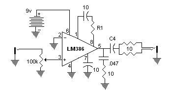
              Trying to go as simple as possible, I've started out breadboarding a LM386 amp. The circuit is pretty much straight from the datasheet except I'm driving both headphones with it.


              It seems to be behaving as if it can't supply enough current to the phones or the phones can't handle the output but neither of those things should be true AFAIK. The output starts to distort at levels lower than I need. I can get the distortion to lessen or go away by turning down the pot but increasing the battery votage to 15v does not help (actually it gets worse) so it's not acting like a headroom thing. I took out the gain components, reducing the gain to 20. It helped a bit but as I noted, I'm not getting the volume I want as is. I've tried both earbuds and Equation RP-21 phones, both of which I've blasted before so I know they can take much higher levels. That said the earbuds definitely distort way more than the RP-21's. Reducing C4 helps (tried 470uf, 100uf, and 10uf) but of course that's also reducing the ouput, especially on the low end. I also tried a 10uf non-polarized just to be sure that wasn't the problem.

              Edit: This wouldn't have anything to do with the crazy transients of a raw pickup output vs. squashed recorded music, would it?
              Last edited by Ptron; 05-08-2011, 05:18 PM.

              Comment


              • #8
                Ok, should've thought of this sooner. Looks like it's the battery that struggles to provide the current, not the lm386 itself. I thought the cap on the bypass pin was enough for testing but apparently it's not. I added some bypass to the 9V "rail" and the distortion was reduced greatly. I'm still getting some distortion on the transients past a certain volume but this now seems to be just your classic lack of headroom distortion since I can reduce it by raising the rail voltage. I'll build this and see how it works in real world (gig) situations. If it's not enough I might look for options that can handle 18V.

                Comment


                • #9
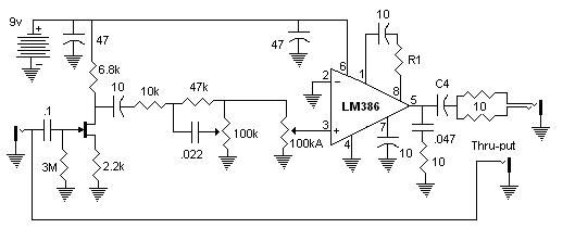
                  Ok, Now we're getting somwhere. More complicated but this works loads better. I put Don Tillman's jfet preamp in front primarily as a buffer. This was because I wanted a tone control and I didn't want the thru-put signal to be loaded down by it. I got the tone control from here. For whatever reason I seem to be able to get more volume without distorting now. Some sort of non-linearity in the preamp resulting in a bit of compression maybe? I think I'll be able to get away with a single 9V battery now.

                  Notes: I currently have R1 bypassed so it's basically zero, i.e. max gain. I'll experiment with bumping this up a bit to make more of the range of the volume pot useable. C4 is 470uf I dropped in a 100uf and couldn't tell the difference but a 10uf started to cut the lows pretty good. I'll probably make the .022 cap larger so I can have more of a high cut for steel but this would probably be pretty good for guitar.

                  Comment


                  • #10
                    Earlier I thought it was some kind of bad grounding -> instability or plain oscillation and was about to suggest a .1 to 10uF (or 100) from pin 6 to pin 4, as close to the chip as possible.
                    I see you added some filtering, don't know how close physically.
                    It seems to have helped anyway.
                    Gain as posted looks too high, specially with the FET gain added, experiment with pulling the 10uF .
                    Power should be enough to melt your brain with any headphone.
                    18V is *too* much.
                    Juan Manuel Fahey

                    Comment


                    • #11
                      Originally posted by J M Fahey View Post
                      Earlier I thought it was some kind of bad grounding -> instability or plain oscillation and was about to suggest a .1 to 10uF (or 100) from pin 6 to pin 4, as close to the chip as possible.
                      I see you added some filtering, don't know how close physically.It seems to have helped anyway.
                      Yeah, On the bread board they were just between the rails but still helped tremendously. I'll put it as close as I can in the actual layout.

                      Gain as posted looks too high, specially with the FET gain added, experiment with pulling the 10uF .
                      Power should be enough to melt your brain with any headphone.
                      18V is *too* much.
                      Hmm. It gets loud enough but I wouldn't call it brain melting. As is, it does start to overdrive a lot when the volume pot gets above maybe 1/4 to 1/3, and then it's louder than anyone should probably listen to for extended periods of time. I'll see if I have a 1M trimpot to use for R1 then I can experiment with it. Personally I'll be using it mostly with the treble rolled all the way off which seems to reduce the gain significantly. I tried it with a 1.8k for R1 and with that and the tone knob most of the way down it was loud, but not crazy loud, and didn't overdrive, even with the volume all the way up. Do you think that's a sign that something's not right?

                      Comment


                      • #12
                        More suggestions

                        First of all...DO NOT GO WITH 18V ! You don't specify which version of the chip you are using, but if you got the plain-jane 386-1 like you get at Radio Shack, it can only handle 12V max.

                        I, too, would check for oscillations...try the bypass cap from pin 6 to pin 4. Oscillations can really make these things sound nasty and can cause the chip to run hot and drain your battery faster.

                        As far as the gain circuit, try using a variable resistor to dial-in the needed amount of gain.

                        I would really recommend you check out the runoffgroove.com Ruby amp project at Ruby and add a headphone jack as detailed in the FAQ at runoffgroove.com FAQ. This should easily make you deaf using any earphones and can drive 4 10" speakers.

                        Comment


                        • #13
                          Originally posted by Zipslack View Post
                          First of all...DO NOT GO WITH 18V ! You don't specify which version of the chip you are using, but if you got the plain-jane 386-1 like you get at Radio Shack, it can only handle 12V max.
                          Oh, no, I meant a with a different circuit, but I did try it with 15V and it seemed to handle it. I wouldn't do it that way permenatnly even if it was rated for it though since I did it with the awkward combination of a 9V and four AA's.

                          Thanks for the heads up with the Ruby circuit. I'll definitely try breadboarding that. So the cap in the gain loop doesn't need to be there? I had assumed it was there to block DC bias voltage or something.

                          Comment


                          • #14
                            386 gain

                            The R-C gain circuit from pin 8 to 1 can probably be left out altogether, or use a pot for the resistor so you can fine-tune it. In my experience, using the gain circuit (with or without the cap) introduced way too much gain and distortion for normal use, especially if you are going to be using an amplified signal like from a keyboard. It's mainly useful for low-level signals like from weak guitar pickups. I also haven't seen a big advantage to having the capacitor in the gain circuit, but it may help with oscillations/distortion. A cap from pins 6 to 4 (right across the chip) can help alleviate oscillations and noise. The Little Gem amp from the same sight is also a decent amp and is a little simpler since it doesn't have the front buffer JFET, but the output volume control is a little awkward and/or expensive. Either one will work well with an ipod with a little tweaking of the gain setting, so they should be okay with a keyboard.

                            Comment


                            • #15
                              I have bitten the bullet and bought one of these I have some more basic stuff to buils before I try something like this. I have a projects book and I am starting off with a low impedance amp

                              Comment

                              Working...
                              X