Hello All, I've purchased a Roland Cube Street. It's a cool little 2 channel, battery powered amp. I want to monitor the mix while playing, but when I plug in my In Ear Monitors, the main speakers go out. The headphone jack is built into the board and is a Jalco PJ9-3C, I think. Anyone familiar with how to override these things? I can use a soldering iron, but I'm not familiar with schematics, etc... and I sure don't want to mess this amp up. Any thoughts?
Ad Widget
Collapse
Announcement
Collapse
No announcement yet.
Override to allow both Headphone and Speaker?
Collapse
X
-
Thanks Tedmich...When I look under the board, I see 7 solder points..What do you you think the connections would be with 7 solder points? Thanks.Originally posted by tedmich View Postits likely a "switched" headphone jack which could be replaced with an unswitched jack, or maybe a jack plus switch so you could turn off the speaker if needed
maybe something like this:

Comment
-
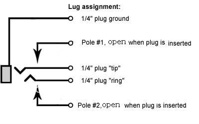
a photo would help diagnosis, it may be like this Cube circuit
The Free Information Society - Roland Cube 40 Electronic Circuit Schematic
using the Jalco picture
JALCO
you's take the switched outputs which go to the speaker and put a DPST switch in between so even with the headphones in you could feed the speaker, it may mess with the amp to feed both but is worth a try.
Comment
-
Thanks all for your feedback. I figured it out. I researched the type of jack (Jalco) and found the schematic. I then soldered two places with wire. It overrides the switch and now I get sound from both places. It was a little loud, so I bought an inline volume control from Radio Shack. It's not real beefy, but it works. Now I'm set to go.
Comment
-
how
Originally posted by cynabel View PostThanks all for your feedback. I figured it out. I researched the type of jack (Jalco) and found the schematic. I then soldered two places with wire. It overrides the switch and now I get sound from both places. It was a little loud, so I bought an inline volume control from Radio Shack. It's not real beefy, but it works. Now I'm set to go.
What pins did you solder?
Comment
-
A quick search on the net and I found where this guy posted the solution to this mod. Apparently soldering pin 4 to pin 5 and then soldering pin 7 to pin 8 is what he said worked. The user name on this other website was "cynabel" so I think we have our OP. Check out this link to his exact post... Post#236
Roland Cube Club (all models) - Page 12 - Telecaster Guitar Forum
Jalco PJ9-3C image was useful too, look at 3C on this image.
When the going gets weird... The weird turn pro!
Comment
-
Did anyone find the schematic for the amp in question, the Roland Street Cube? I've been looking at ss amp schematics recently and the headphone jack switching is sometimes rather complicated, in particular to accommodate the lower volume necessary for the headphones. cynabel mentioned that by jumpering the jack terminals the headphone output was loud so he purchased an in-line volume control from Radio Shack.
One arrangement I've seen runs the (+) output to both the headphone and the speaker through the switching jack while using an attenuated (-) output for the headphone and the full (-) output for the speaker.
cynabel's post at TGF: "OK, I figured it out. I found the Jalco 1/4 inch jack socket schematic. I had to remove the board and underneath, took short pieces of wire and soldered pin 4 to 5 and pin 7 to 8. This overrides the switch and you get sound at the speaker and the headphones. Now all I need is a volume control for the IEM's and I'm set to go. FYI."
I have a hunch that one of the two jumpers added connected the headphones to the full output signal. Just a hunch but I would bet a nickel that I am right...
Steve Ahola
P.S. I suspect that the headphone switching for the other small Roland Cube amps of the same era would be similar so looking at schematics for those amps might be helpful.Last edited by Steve A.; 05-09-2013, 01:46 AM.The Blue Guitar
www.blueguitar.org
Some recordings:
https://soundcloud.com/sssteeve/sets...e-blue-guitar/
.
Comment
-
hi i was just reading this post on modding the street cube to use the headphone jack and speaker at the same time. im just wondering if you can give me some direction on how to access the underside of the pcb board that the headphone jack is attached to. Ive tried going in through the front via speaker holes, and ive tried removing various screws form the side and back of the amp but the black metal housing wont budge, I know theres some screws I don't need to touch and it would be detrimental to remove.
any tips or info?
thanks for your time, any help appreciated.
Comment
-
I don't know that model myself, but in many small amps, the screws that hold the handle on top also hold the chassis in. In a photo I also see four regular screws along the bottom edge of the rear panel, those too. I am still voting for the handle screws.
Oh, and a lot of times, even when the chassis is free, it can stick in there. The tolex on the cabinet sticks to the chassis.Education is what you're left with after you have forgotten what you have learned.
Comment
Comment