 Tweet
Tweet
When using a CCS as an active load for an AC coupled [source/emitter/cathode] follower - how do you calculate what the corner frequency of your HPF is?
-
The prince and the count always insist on tubes being healthy before they're broken -
Please post the schematic of what you intend to build, labelling paarts for reference ((such as R1 , R2 .... C1 , C2 .... etc.)Juan Manuel Fahey -
I second that.
The follower has very low output impedance for small signals, roughly 1/gm, irrespective of whether it's loaded by a CCS or a resistor. So it's the resistance of the load it's driving that determines the corner frequency.
For large signals, things will get interesting as the follower starts to cut off on negative peaks. But we're now in nonlinear world, and corner frequency is a concept that belongs to linear world."Enzo, I see that you replied parasitic oscillations. Is that a hypothesis? Or is that your amazing metal band I should check out?"Comment
-
Ok, now we're making sense.Originally posted by Steve Conner View Post
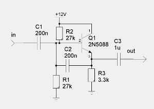
Bootstrapped follower A:
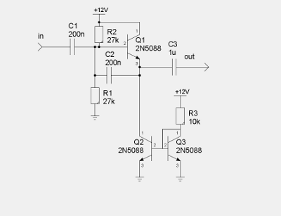
Bootstrapped follower B with CCS load:
In figure A with the 3.3K load resistor, I had calculated the corner frequency at 48Hz (and the input at 58Hz since the bias resistors are effectively paralleled)
In figure B, I wasn't really sure how to figure it - but your reply brings up another question I was mulling - what determines the corner frequency for the bootstrapping? The actual resistance values or the effective input impedance of the follower?
This is just an example, but in at least one application - I was hoping to get a free pole of HPF out of my buffering. Like say 50Hz for piezo pickups on guitar - there the input resistors are a bit higher but still trying to take advantage of bootstrapping to lower noise of the circuit its replacing.The prince and the count always insist on tubes being healthy before they're brokenComment
-
The output corner frequencies of both these circuits are undefined because you haven't specified a load resistance. You don't know what is completing the circuit with C3 in it.
Good design calls for the load resistance to be large compared to Figure A's R3, so it follows that the load resistance mostly controls the corner frequency and R3 only has a tiny effect. (It also follows that swapping it for a CCS won't make much difference either.)
As for the input, when you hook up a piezo, the capacitance of the piezo itself determines the HPF pole along with the input resistance of the preamp. A typical value might be 1000pF."Enzo, I see that you replied parasitic oscillations. Is that a hypothesis? Or is that your amazing metal band I should check out?"Comment
-
The question itself is more an academic curiosity when I realized "oh wait, what IS the frequency (Kenneth)". But... since the output of the follower is (usually) very low impedance compared to the load, wouldn't the FOLLOWER set the filter frequency rather than the load? The idea of the CCS came up because one of the stages was a differential amp, and once you have one half of a current mirror, well.... the whole world starts to look like a nail.
True to form, I have about three projects in mind in various stages of design (on the short list). One is the piezo breakout box. The other place the buffer came up was an amp where I thought... I'm sticking all my controls and externals on a board up front anyway. I hate the idea of running high impedance stuff off board. So I thought - why not stick a bootstrapped JFET source follower right at the jack, we can get a free guard band while we're at it, a low impedance line to snake back to the first tube gain stage, and drop the input resistor from 1M to like 33K for lower self noise. The differential amp came from thinking - if I feed the differential amp from tip and ring, if it's a mono jack, the signal is just unbalanced, but with a TRS plug, I can run balanced line from the guitar. But I've scrapped that idea for now, and just going with the buffered jack.The prince and the count always insist on tubes being healthy before they're brokenComment
-
No, quite the contrary.since the output of the follower is (usually) very low impedance compared to the load, wouldn't the FOLLOWER set the filter frequency rather than the load?
Being very low impedance, and in series with the load, "it puts itself out of the equation" and leaves the coupling capacitor plus the load impedance (which you don't state ) as the important elements.
It also scratches me the wrong way when you repeat time and again the word "impedance" and leave it at it.
Please always refer to the R and the C in the RC cell which defines frequency response (or poles).
Basically the same as Steve wrote, only seen from another angle.
EDIT: I forgot (and also seen from another angle).
You can (and should ) consider the bipolar transistor as a transformer, in this case an impedance transformer , and the "impedance ratio" is Beta or Hfe , the current gain.
So at the emitter you have 27K//27K or 13K divided by Hfe, which in any decent small signal transistor is often ariund, say, 300 , so at that emitter you have it reflected as 13000/300=43 ohms.
Which are in parallel with the 3K3 emitter resistor , so total value is , say, 1% less.
If you replace the 3K3 resistor with a perfect, infinite impedance current source, then it's the plain 43 ohms, just the burger without the fries or Coke.
Which is about the same
So those 43 or 42.5 ohms are *nothing* compared to any properly dimensioned load, which should be at least 4K7 or higher given your values choice.
Hope this makes things clearer from a practical point of view.Juan Manuel FaheyComment
-
'Being very low impedance, and in series with the load, "it puts itself out of the equation" and leaves the coupling capacitor plus the load impedance (which you don't state ) as the important elements.'
On a side note, I sometimes fall into the opposite trap and forget to include the source impedance as being part of the 'R'.
When considering a 12AX7 common cathode gain stage, this can lead to significant error.
PeteMy band:- http://www.youtube.com/user/RedwingBandComment
-
Your feedback/bootstrap is done strangely. Usually, the lower base resistor is split into 2 resistors, and the bootstrap cap goes to the junction. This technique can be very effective when implementing a JFET buffer. Of course, if you used a JFET buffer, you wouldn't have to worry about input impedance anyway. If you really want to get fancy, use a JFET input stage and put a resistor in series with the drain. Drive an op amp with a gain of one from the output of the JFET buffer, and then connect the op-amp output to 2 caps--one to the drain, and the other to a split gate resistor. If you do this correctly, you can get AC input impedances into the gigohms.Comment
Comment