Ad Widget

Collapse

Announcement

Collapse
No announcement yet.

Matching JFETs for piezo buffer preamp

Collapse
X
 
  • Filter
  • Time
  • Show
Clear All
new posts

  • Matching JFETs for piezo buffer preamp

    I want to build the Alex Rice Piezo Preamp (Alex Rice Piezo Preamplifier | Zach Poff (schematic included)), but need to match the JFETs.

    I've found several ways to do this on the Internet, but all require extra parts which I don't have right now. Someone suggested that the matching setup must be as close as possible to the real setup.
    So I thought: Is it possible to just build the preamp on a breadboard (which I do have) and use that to match the JFETs?
    And if so what do I have to measure?
    And if this is not possible, what would be the best alternative?

    Thanks in advance.

    Hans
  • #2
    If you breadboard the circuit put a resistor of 1k or so in series with XLR2 and XLR3 (one in each leg) and connect the free ends to a +ve regulated voltage supply and the -ve end to circuit ground. Then measure the voltage difference between the drains of Q1 & Q2. Match your FETs by swapping them out to get as close to 0v as possible. You can keep one in place and just switch the second.

    Connect both inputs to ground to kill noise.

    Comment


    • #3
      The web site you linked recommends this: http://geofex.com/Article_Folders/fetmatch/fetmatch.htm method for JFET matching. Have you tried it?

      Mark

      Comment


      • #4
        Thanks for the replies.
        I will go for the method Mick suggested.
        @MarkusBass: I've read the article, but I don't have a opamp lying around at this moment, that's why I'm trying to use the breadboard method first.

        Hans

        Comment


        • #5
          You should be able to match the breadboarded circuit off a 9v or 12v battery, but if you need to power it from a higher voltage (48v) then increase the 1k resistors I suggested. 6.8k is fairly common in phantom circuits, but something close would be fine. 10k would do.

          Comment


          • #6
            Thanks for the replies.
            I've build the circuit after matching the JFET's and it works fine, although I needed (a lot) more output for what I want so I ended up fiddling with this design and the original Tillman Cable Preamp FET Preamp Cable.

            I doubled the Tillman circuit (minus the 20K resistor at the gate) to make it balanced (using matched FET's), and connected a 150 Ohm resistor and 220nF cap between XLR2 and 3. It seems to sound fine.

            Thanks again for the help.

            Comment


            • #7
              Glad you sorted it out

              That circuit probably works and sounds very good, but requires a lot of homemade balancing to work.
              FETs being the inconsistent little buggers they are, will force you to go through *many* until you find a few which match.

              Personally I'd try to design an Op Amp based preamp, which would need no matching and provide asily adjustable gain to boot.
              And could still be built very small by using SMT parts.
              Juan Manuel Fahey

              Comment


              • #8
                It took some time to measure the JFET's, but I've put a small piece of masking tape with a number on each JFET and put my data in a spreadsheet, to find a matching pair is now relatively simple.

                The circuit indeed sound great.

                Comment


                • #9
                  Necro post - but it's the one I'm looking at:

                  I'm trying to simulate this circuit and not getting very far. I was mostly trying to do so to make sure that my operating points were compatible with my part selection, but I'm getting very low gain out of it, the zobel network appears to roll of far less than expected, and far higher, and any attempts at the DC blocking caps on the actual piezos result in unusable amounts of rolloff.

                  BTW - Linear's LSK489 seems to be a handy matched pair JFET if I can make it work here.
                  The prince and the count always insist on tubes being healthy before they're broken

                  Comment


                  • #10
                    Originally posted by NateS View Post
                    I'm trying to simulate this circuit and not getting very far.
                    Can you post the simulation?
                    Originally posted by NateS View Post
                    I was mostly trying to do so to make sure that my operating points were compatible with my part selection, but I'm getting very low gain out of it, the zobel network appears to roll of far less than expected, and far higher, and any attempts at the DC blocking caps on the actual piezos result in unusable amounts of rolloff.
                    So you are talking about real, assembled circuit, right? What do you mean by "attempts at the DC blocking caps"? Changing them, or what?

                    Mark

                    Comment


                    • #11
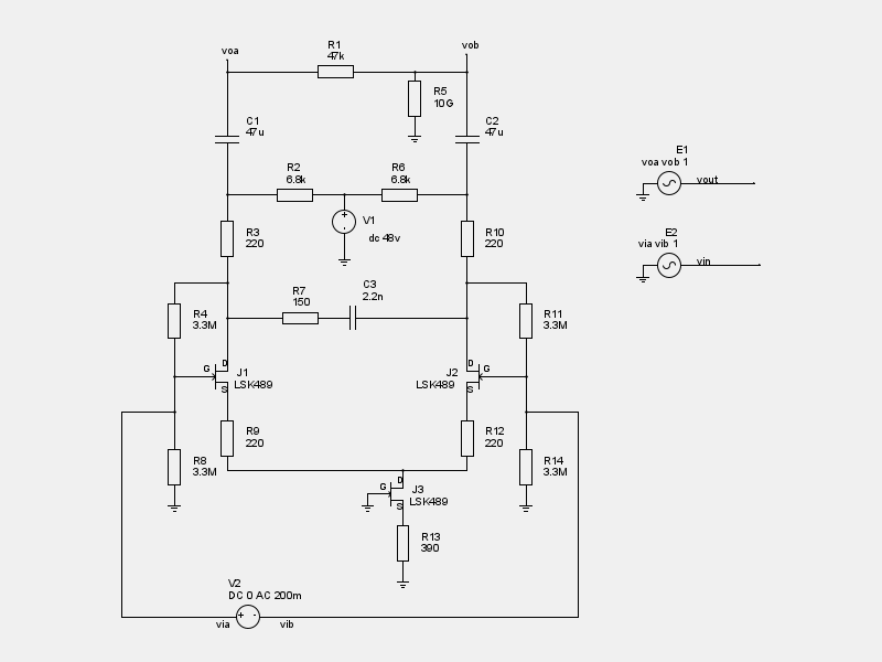
                      No - I'm simulating only so far. I'm working from Smugerd's version of it. (Phantom Piezo Preamp | Stompville) I think I had some problems where my jfet symbol pin order was broken. Fixed that, but I'm still not getting unity gain out of it. Here's mine:


                      * Spice netlister for gnetlist

                      .MODEL LSK489 NJF BETA=0.035 VTO=-0.54 LAMBDA=5.0E-3
                      + IS=3E-14 N= 1 RD=8 RS=7 CGD=5E-11 CGS=5E-11
                      + PB=1.2 FC=0.5 KF=0 AF=1

                      .control
                      op
                      plot db(vout/vin)
                      .endc

                      R5 vob 0 10G
                      R1 voa vob 47k
                      R2 7 1 6.8k
                      R6 1 8 6.8k
                      R7 4 2 150
                      R10 8 3 220
                      R3 7 4 220
                      R12 6 9 220
                      R9 5 9 220
                      R4 4 via 3.3M
                      R8 via 0 3.3M
                      R14 vib 0 3.3M
                      R11 3 vib 3.3M
                      R13 10 0 390
                      J3 9 0 10 LSK489
                      E1 vout 0 voa vob 1
                      C2 8 vob 47u
                      C1 7 voa 47u
                      E2 vin 0 via vib 1
                      J2 3 vib 6 LSK489
                      J1 4 via 5 LSK489
                      C3 2 3 2.2n
                      V1 1 0 dc 48v
                      V2 via vib DC 0 AC 200m
                      .END

                      In dc simulation, J3 biases up to 900ua - I didn't want to go much lower because the noise curve starts to trend up sharply below 1mA. But the page cited above, he says the gain into a 47k load should be about 15db.
                      The prince and the count always insist on tubes being healthy before they're broken

                      Comment


                      • #12
                        What software did you use? Is it LTSPice? If yes, please post the simulation file. I think that V2 voltage source is used incorrectly. There should be capacitors between the voltage source and JFET gates. And the V2 voltage source should be used in a different way.

                        Mark

                        Comment


                        • #13
                          In the meantime I checked it. The circuit works correctly. The gain is +18.8dB. The input voltage has to be connected through capacitors (I used 47nF) and the C3 capacitor has to have lower value (like 220p) - unless you increase value of R7.

                          EDIT: C3 = 1nF causes 1.6dB gain loss at 10 kHz. I would leave 1 nF.

                          This sentence also requires some clarification:
                          Originally posted by NateS View Post
                          In dc simulation, J3 biases up to 900ua - I didn't want to go much lower because the noise curve starts to trend up sharply below 1mA. But the page cited above, he says the gain into a 47k load should be about 15db.
                          Are you aware that when you have 900uA through J3 it results in 450uA through each transistor? Initally, it was set up higher.

                          HTH,
                          Mark
                          Last edited by MarkusBass; 06-19-2017, 08:42 AM.

                          Comment


                          • #14
                            I'm using ngspice. And I feel so stupid. A few years ago I was modelling switching power supplies in ngspice. Now I couldn't remember that 3.3M resistors are actually 3.3 milliohms, they need to be 3.3 MEG. Doh, looks a bit more reasonable now.
                            The prince and the count always insist on tubes being healthy before they're broken

                            Comment


                            • #15
                              It's a common mistake in SPICE programs - don't worry. Now you will remember for the next few years . You need to add the input capacitors and provide the input signal(s) in a slightly different way.

                              Mark

                              Comment

                              Working...
                              X