Announcement

Collapse
No announcement yet.

Test bench amp setup advice

Collapse
X
 
  • Filter
  • Time
  • Show
Clear All
new posts

  • Test bench amp setup advice

    Hi
    Thought I'd pick the brains of you more experienced than I am techs. On my bench I have been using a Harmon Kardon AVR 25ii receiver/amp for listening to radio and as a signal source for testing amps. I just ran a cable from the REC out into a volume pot, then to a female jack socket for a signal source.
    I then also run the stereo speaker outputs to a patch bay, so that I can manually connect my shelf speakers to it, or test an external speaker cab with it.
    The unit can do about 75W per channel.
    On the AUX input on the rear, I have a cable with a high voltage cap going to a signal tracing probe, to trace valve amps etc.
    On occasion I have noticed that while signal tracing a high voltage section on an amp, the protection circuitry in the receiver kicks in and switched itself off. Annoying at times. I have also noticed the preamp frontend clips very easily.
    My question is, is it ok to use the AV unit as I am doing, or should I rather use another basic power amp for my signal tracing needs?
    Just seemed a bit of an overkill to use it only for listening to radio.
    Any help will be VERY much appreciated.
    Regards
  • #2
    To check out preamps the Tape in or Aux input is the same spec as a power amp input. Line level. What you have is basically what I had on my bench for decades. Some amps' protection circuitry are more sensitive than others. I suspect you are spiking some DC into the amp and it is detecting an instantaneous offset. I rarely used a signal tracer. I used an oscilloscope. But... When I used a signal tracer it was a little battery powered job with headphones. Completely isolated and simple. Really just a few discrete components. I've seen signal tracer circuits using an op amp:
    Signal tracer circuit. - Electronic Circuits and Diagram-Electronics Projects and Design

    Comment


    • #3
      Originally posted by olddawg View Post
      ...Some amps' protection circuitry are more sensitive than others. I suspect you are spiking some DC into the amp and it is detecting an instantaneous offset. I rarely used a signal tracer. ...
      I agree that is probably what is happening with your setup. To prevent the large spike that occurs when the DC blocking cap is initially charging you could put together a circuit such as the attached example. The circuit is just one of many ways to do this. I'm showing one way using components that would already be available in a shop. The 10k resistor limits the charging rate of the blocking cap when the diodes are conducting. The diode arrangement limits the signal into your monitor amp to a maximum of plus or minus 1.2V. This will allow a 2.4Vpp AC signal for signal tracing. You could stack additional diodes or use zeners instead if your monitor amp will take more without overload. Just experiment.

      Click image for larger version

Name:	DC Block with Clamp.JPG
Views:	1
Size:	10.0 KB
ID:	840443

      Comment


      • #4
        Thank you olddawg and Tom Phillips.
        Tom, I actually have that exact circuit installed in my probe already. I use two anti-parallel led's.
        I think I'm gonna scrap the signal tracer idea completely. Instead I'm gonna force myself to use my scope more.
        Is this a good motto to use you think?

        Comment


        • #5
          It's up to you but if you like using the signal tracer so that you can hear the signal then there are solutions to be found. The problem is the issue with your monitor amp shutting down. If you do not want to add a new separate dedicated signal tracer then maybe your scope has an output that can feed the amp. This was discussed in the thread at http://music-electronics-forum.com/t41004/ . See posts #6, 7 & 15. If it works for you then you can have a scope display and signal tracer audio simultaneously.

          Comment


          • #6
            Originally posted by Tom Phillips View Post
            I agree that is probably what is happening with your setup. To prevent the large spike that occurs when the DC blocking cap is initially charging you could put together a circuit such as the attached example. The circuit is just one of many ways to do this. I'm showing one way using components that would already be available in a shop. The 10k resistor limits the charging rate of the blocking cap when the diodes are conducting. The diode arrangement limits the signal into your monitor amp to a maximum of plus or minus 1.2V. This will allow a 2.4Vpp AC signal for signal tracing. You could stack additional diodes or use zeners instead if your monitor amp will take more without overload. Just experiment.

            [ATTACH=CONFIG]37024[/ATTACH]
            Hi Tom.
            Just out of curiosity, why use diodes? Would A simple resistor divider not work?
            Thank you for your circuit. I have built it, and it works a charm. I can now inject a 30 V dc without it switching off.
            I will also be making myself a cable to hook up to the ch1 Vertical out of my scope. That way i will have the added benefit of a normalized signal level and increased input impedance.

            Comment


            • #7
              Originally posted by Tom Phillips View Post
              To prevent the large spike that occurs when the DC blocking cap is initially charging you could put together a circuit such as the attached example. The circuit is just one of many ways to do this. I'm showing one way using components that would already be available in a shop. The 10k resistor limits the charging rate of the blocking cap when the diodes are conducting. The diode arrangement limits the signal into your monitor amp to a maximum of plus or minus 1.2V.
              This is an old thread, but I am reviving it to ask a question of Tom.

              I had bookmarked this thread meaning to build the diode clamp circuit at some point; in fact I just built & tested it today. It's to go with a signal tracer that I use on tube amps and various other circuits. In my case the tracer goes to a USB sound card, so I am only using one diode in each direction as the sound card is a bit more tender about input voltage than the OP's bench amp. It will be useful to me - I once zapped (probably killed a transistor or IC or both, haven't checked yet) a small Radio Shack battery powered amp that I was using with the signal tracer, by forgetting when I was looking at some ripple on the reservoir cap of a B+ supply that the ripple P2P was up around 4VAC or so.

              My question has to do with the 10K resistor - when I put it in circuit it dropped the voltage considerably which is what I would have expected - from about 1.2VAC average (my meter doesn't do RMS) to maybe 625mV. I know of some DIY designs for attenuators to protect computer or USB soundcards when using PC scopes - they combine resistors plus the diode clamp. In your comment to the OP you explained that the resistor is to prevent a spike while the blocking cap initially charges. Is this something I would care about for my purposes - i.e. going into a USB or computer soundcard that likely does not have protection circuitry of the sort that the OP was asking about? I have a notion that soundcards typically have their own blocking caps already but am not certain of that.
              Last edited by Usable Thought; 01-18-2016, 05:27 PM.

              Comment


              • #8
                If I may?

                "Breaker on the side" as they used to say in my CB days.

                Originally posted by diydidi View Post
                Would A simple resistor divider not work?
                A divider would always give you a proportional output voltage to that going in, so you'd need to scale the divider ratio based on assuming a maximum signal level. It would then become proportionally less sensitive at low signal levels. Because you wouldn't necessarily always know the maximum amplitude of the input signal, you'd have to guess the divider ratio and build in a safety margin. Diodes clamp the output voltage level, so the maximum output can only be the sum of forward voltage drops and no more, regardless of the input level.

                In response to Usable Thought; the 10k resistor reduces blocking cap surge, but also has another important function in limiting the current through the circuit and needs to be included. As far as AC is concerned the capacitor doesn't exist, and the diodes conduct once their forward voltage drop is overcome. Without the 10k resistor the circuit would short out the signal source at anything above the combined diode voltage drop and could cause excess current draw.

                Another important point is the positioning of the blocking cap - it needs to be included because you may be reading AC superimposed onto DC. You don't want that DC appearing across the clamping diodes. In a tube amp this could be excessive. So regardless of whether your sound card has an input cap, you need the blocking cap where it is.

                Comment


                • #9
                  Originally posted by Mick Bailey View Post
                  In response to Usable Thought; the 10k resistor reduces blocking cap surge, but also has another important function in limiting the current through the circuit and needs to be included. As far as AC is concerned the capacitor doesn't exist, and the diodes conduct once their forward voltage drop is overcome. Without the 10k resistor the circuit would short out the signal source at anything above the combined diode voltage drop and could cause excess current draw.
                  Don't worry about the blocking cap - that is in my tracer probe & not about to come out! I only mentioned the possibility of such caps existing in sound cards because it seemed possibly relevant, possibly not.

                  And thanks for stepping in and answering my question. However do I really need the resistor? I'm still not clear. The usage will be such that at most, the AC voltage is going to be little if any more than what I mentioned burned out my little Radio Shack amp - e.g. ripple of say 4VAC which is more than the USB soundcard's line input can handle (something like 2VAC is its max, though I ought to hunt around to find the exact spec). Even when I tested the diode clamp, sans resistor, with a 9VAC wall wart - much higher than I would ever expect to encounter in actual use with my signal tracer - I didn't notice smoke, excess humming of the wall wart, or whatever other bad thing might be expected to happen with big current draw. I am looking at plates, grids, etc., and only now and then at things like HT reservoir cap where ripple would be high - never at mains or what have you, God forbid.

                  If current were still a concern even with the above caveats, then I would rather do it this way: fuse the device, plus add a suitable switch to swap the resistor into circuit - to be used only if the fuse goes on me & after replacing it I want to look at whatever voltage point did that. If I did it that way, what would be an appropriate value for the fuse? I am thinking something like a 0.5A fast-blow but am foggy about why I think that.

                  OR - could the resistor be put into series w/ the parallel branch that contains the diodes? That way it would only come into play if the diodes start conducting. Tom's schematic doesn't show it that way but that would make some sense to me - although frankly I like my approach better, because if I can size the fuse nicely, then I get a heads-up even if I am using my spectrogram app which doesn't show voltages.

                  The simple reason for being so fussy is that most of the time I won't be looking at excess AC voltage - and I don't want the resistor's voltage drop to interfere with ordinary observations using my spectrogram app. No need to knock down the amplitude 100% of the time when the diode clamp would only come into play something like 0.5% of the time. But I do want the device in circuit to prevent those "oops" moments when I forget to turn down the input volume on the soundcard.

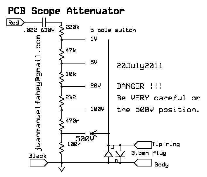
                  Another possibility is that I could get a rotary switch & build the full attenuator that JM Fahey described, complete with resistors of given sizes and a switch w/labels to indicate what is in circuit - this was in a thread over on The Gear Page on USB scopes. Not sure if I want to do that yet, though, since for one thing I am not using a PC scope! Note, if you look at his contributions on that thread you may notice that one or two of the GIFs or JPEGs of schematics he posted show as broken links - or at least they do in my browser for some reason. For me the images are still there if I right-click on them to open them in a separate browser tab. Anyway I saved a copy for myself quite a while ago - so below is JMF's schematic of a DIY attenuator including diode clamp for use with PC or USB scope:

                  EDIT: I am re-reading the Gear Page thread & getting confused. JMF's attenuator with its switched resistors in paralle looks very different than Tom's series resistor. Also, in my own experience, if one is careful to keep the input volume on a USB soundcard low - just in case - there is never any problem at all looking at 99 percent of the voltage points in a tube amp. You can even look at the big ripple on the H+ reservoir cap, if you remember to turn down the soundcard's input volume first. So I don't expect to be looking at the higher AC voltages the attenuator is meant to handle.

                  But at any rate JMF's idea is more attractive to me because it is more flexible - PROVIDED that one has some idea what the heck one is looking at. Judgement is needed to choose which resistor to switch in. But then as I say a fuse to go with the clamp might handle at least a low-grade "oops" without any squashing of signal when looking deliberately at low voltages.

                  Last edited by Usable Thought; 01-20-2016, 11:12 AM.

                  Comment


                  • #10
                    Even when I tested the diode clamp, sans resistor, with a 9VAC wall wart - much higher than I would ever expect to encounter in actual use with my signal tracer - I didn't notice smoke, excess humming of the wall wart, or whatever other bad thing might be expected to happen with big current draw.
                    Is the DC blocking cap reactance limiting what the diodes are seeing? Just a though. What's your cap value?

                    Juan's attenuator is very similar to those incorporated in 50's tube voltmeter designs, but with the addition of the clamping diodes that wouldn't be necessary when driving a triode in a voltmeter. It's a good way of doing things and has multiple uses. It offers additional flexibility because of combining a voltage divider (with inherent current-limiting) and diode clamping. I don't see it as too dissimilar to Tom's proposal; if you were to connect a resistor to ground from the 10k resistor to create a divider, you'd have an equivalent circuit to JMF's

                    As far as attenuators go, unless you're certain of the voltages in your circuit (say, a 9v pedal) then it's a good habit to always select the highest range and step down, and to always leave the attenuator set to its highest range.

                    If you want to include a fuse, it shouldn't be greater then the diode current rating. I think if your blocking cap is large enough to pass 60Hz or 120Hz then you'd need to limit the current through the diodes, otherwise the fuse would nuisance-blow. If you're confident that this wouldn't occur regularly for your own measurements, then I'd go as low as 100mA.

                    Comment


                    • #11
                      Originally posted by Mick Bailey View Post
                      Is the DC blocking cap reactance limiting what the diodes are seeing? Just a thought. What's your cap value?
                      The cap is 0.002uF, as recommended by Bill Machrone of BillM Audio in his page on building a signal tracer. This may be a small value for a blocking cap, I don't know; but it has worked well for me.

                      01/21/16 EDIT: Hmm, it seems MUCH too small a value to let through 50 to 60Hz . . . I may start a separate thread asking about this.

                      Originally posted by Mick Bailey View Post
                      f you want to include a fuse, it shouldn't be greater then the diode current rating. I think if your blocking cap is large enough to pass 60Hz or 120Hz then you'd need to limit the current through the diodes, otherwise the fuse would nuisance-blow. If you're confident that this wouldn't occur regularly for your own measurements, then I'd go as low as 100mA.
                      Well, I do see 60Hz and 120Hz just fine with this cap - I don't know whether I'm supposed to or not but they show up quite visibly on my spectrogram when present.

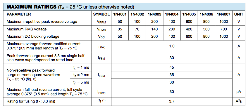
                      For the clamp diodes I used 1n4005 - Vishay's data sheet appears to show that for all the 1n400x diodes, maximum average forward current is 1A - so would my half-amp fuse be okay? I can get a half-amp fuse at my local Radio Shack but have never seen 100mA fuses there and don't really want to pop another $6 in shipping from Mouser or DigiKey until I have something else to order from them.

                      Last edited by Usable Thought; 01-21-2016, 06:54 AM.

                      Comment


                      • #12
                        The reactance of a 0.002uf cap at 60hz is 1.326M ohms, so your circuit was seeing a much reduced voltage and current when connecting your wall-wart.

                        500ma for a fuse is fine. If you're sticking with the coupling cap value you shouldn't have any problems as the cap will limit the current under most circumstances. You have to bear in mind the reactance when viewing mixed-frequency signals for subsequent analysis. Higher-frequency signals will appear to have greater amplitude.

                        Comment


                        • #13
                          Originally posted by Mick Bailey View Post
                          You have to bear in mind the reactance when viewing mixed-frequency signals for subsequent analysis. Higher-frequency signals will appear to have greater amplitude.
                          Thanks for looking at this - that's helpful to know.

                          My guess is, in the past this hasn't been a problem because the way I use the spectrogram app is not to establish absolute amplitudes at any given frequency, but only to obtain an overall noise profile, or snapshot, for a particular node; since all such snapshots are taken with the same setup, they then be compared to other nodes. The distortion of amplitude is consistent from node to node, so the usefulness is still there.

                          But I'm wondering if it wouldn't be better at some point to tear down my DIY probe and install a higher-value cap to get a somewhat less distorted pass-through. It sounds like it would then let through more voltage & current and I'd have to do things such as add attenuating resistors etc. to continue to protect the soundcard.

                          I found this online calculator for help w/capacitor values & low frequency passing - plus I would need to read up far more carefully on the entire subject. Also I might want to bear in mind that trying to get a really flat, accurate probe + soundcard is apparently rather involved, and for my simple purposes probably not worth the effort - while Googling I came across pages where audiophiles discussed highly elaborate devices for making accurate measurements - e.g. this soundcard interface designed by Pete Millett.
                          Last edited by Usable Thought; 01-21-2016, 09:01 AM.

                          Comment


                          • #14
                            If you want greater accuracy you'd need to size the blocking cap accordingly to reduce the effects of reactance,

                            With a resistive attenuator the capacitor forms a high-pass filter in conjunction with the resistance, so the cutoff frequency and blocking cap size are determined by the resistance.

                            Comment


                            • #15
                              The .022 cap I suggested cuts below 30Hz, so it's flat for Guitar and Bass frequencies, what we are interested in, and small enough to limit energy of current peaks when touching a plate or supply rail a couple hundred volts above ground, a reasonable compromise in my mind.
                              Will show 50/60Hz quite well (maybe attenuated by 1 or 2 dB)

                              Voltage peaks will be current limited by the 220k series resistor , notice it's always in the path, I did NOT provide an extra sensitive direct (no attenuation) switch setting, all for safety, plus diodes will clamp any dangerous level.

                              Not dissing Bill M , quite the contrary, I understand his choice of a very small cap for an *acoustic* (not scope) signal tracer, going through a very small, battery powered speaker, some 2" diameter in a cigarette case sized box, in that case the idea is to hear whether there is or not some guitar signal present at some stage, plus hearing gross distortion/motorboating/buzz/hiss.
                              Not really suitable to hear hum, which the tiny speaker wouldn't reproduce anyway so his choice is fine.
                              Juan Manuel Fahey

                              Comment

                              Working...
                              X