I may have posted about this before, but I couldn't find anything quickly looking through my posts. I apologize if I posted about this before, but I'm whipped up a cable for a buddy of mine and thought I'd share some photos of how I do it. If anyone was so inclined, it might save them quite a bit of money on buying a high end cable.
Here is the parts and supplies I used for the job:
• Canare GS-6 instrument cable (blue) Canare GS-6
• G&H Bigfoot 1/4" plug, 2 conductor .322" exit hole*(I think) G&H Bigfoot 1/4" plug
• 63/37 eutectic solder (just my preference, 60/40 is fine)
• liquid rosin flux (will make this job a lot faster and smoother)
• alligator clip or heat sink clip
• solder helper tool(s) Velleman 6pc Soldering Aids
• NTE Dual wall 3:1 heatshrink w/adhesive 3/4" dia. NTE Heatshrink Tubing
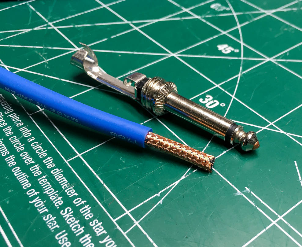
First thing I do is make a visual measurement of how much exterior covering I need to remove. I mark it with a black sharpie and use an Xacto blade to carefully make the cut in the covering. I make sure to remove only what is needed, and leave enough for the metal tabs on the plug to grip onto. Importantly, using a new or sharp blade, you do not need to use much pressure at all to cut the depth that you want. In fact, it is best not to cut all the way through and risk damaging the shield or any other part of the cable. May take some practice to get right.
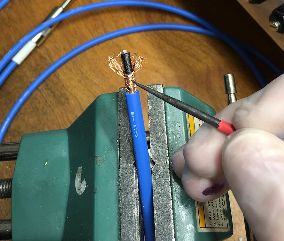
Then, using the solder pick tool (or similar dental tool, etc), I carefully unbraid the copper shield:
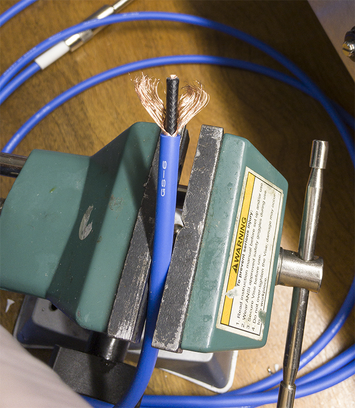
With the shield unbraided, you'll notice a black covering separating the shield and inner insulator. This is a conductive material designed to minimize triboelectric noise. Remove this carefully using wire strippers. Remove enough to fully expose the inner insulator (see photo below for an example).
I then use wire strippers to remove enough inner insulator to expose enough copper to fit through the solder tab hole and contact the center conductor of the plug.
To do this without destroying your bench in a fit of anger and frustration, pre-tin both the shield and inner conductor of the cable.
Here is where the liquid flux comes into play. Coating the copper with some flux will allow you to flow solder onto the copper very quickly and prevent burning or melting the insulating coverings.
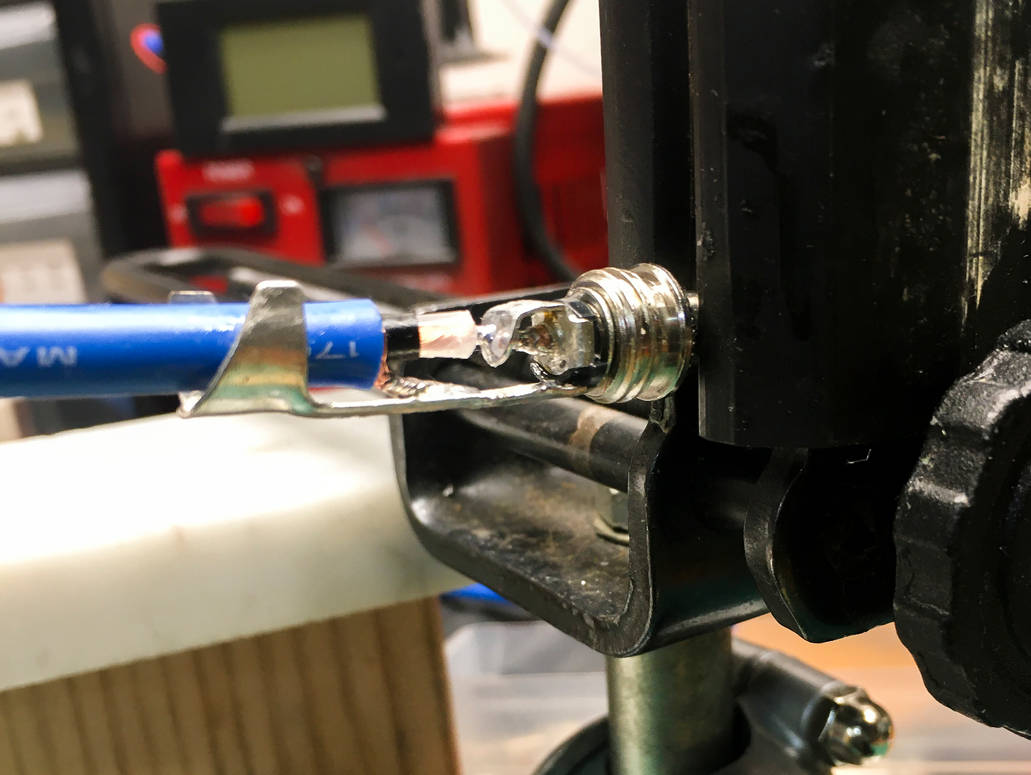
One thing to note – it can be helpful to wedge a small alligator clip, or flathead screwdriver head in between the shield and center conductor to keep them separated when soldering the center conductor.
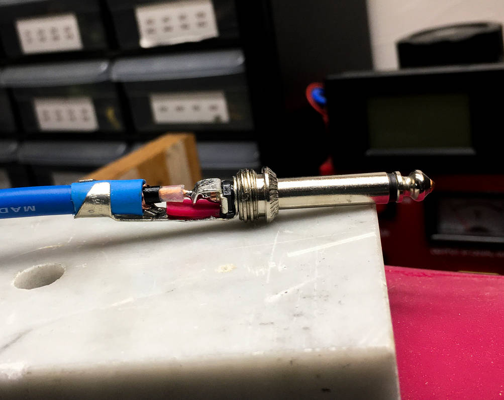
I also use a small piece of standard heatshrink between the metal strain relief tabs on the plug as added protection for the PVC cable covering. So far it should look like this (as an added step, I use a small piece of silicone baking sheet, cut the width of the plug tabs, to insure there is no short and help keep them in mechanical alignment... it's probably overkill.):
continued below....
Here is the parts and supplies I used for the job:
• Canare GS-6 instrument cable (blue) Canare GS-6
• G&H Bigfoot 1/4" plug, 2 conductor .322" exit hole*(I think) G&H Bigfoot 1/4" plug
• 63/37 eutectic solder (just my preference, 60/40 is fine)
• liquid rosin flux (will make this job a lot faster and smoother)
• alligator clip or heat sink clip
• solder helper tool(s) Velleman 6pc Soldering Aids
• NTE Dual wall 3:1 heatshrink w/adhesive 3/4" dia. NTE Heatshrink Tubing
First thing I do is make a visual measurement of how much exterior covering I need to remove. I mark it with a black sharpie and use an Xacto blade to carefully make the cut in the covering. I make sure to remove only what is needed, and leave enough for the metal tabs on the plug to grip onto. Importantly, using a new or sharp blade, you do not need to use much pressure at all to cut the depth that you want. In fact, it is best not to cut all the way through and risk damaging the shield or any other part of the cable. May take some practice to get right.

Then, using the solder pick tool (or similar dental tool, etc), I carefully unbraid the copper shield:


With the shield unbraided, you'll notice a black covering separating the shield and inner insulator. This is a conductive material designed to minimize triboelectric noise. Remove this carefully using wire strippers. Remove enough to fully expose the inner insulator (see photo below for an example).
I then use wire strippers to remove enough inner insulator to expose enough copper to fit through the solder tab hole and contact the center conductor of the plug.
To do this without destroying your bench in a fit of anger and frustration, pre-tin both the shield and inner conductor of the cable.
Here is where the liquid flux comes into play. Coating the copper with some flux will allow you to flow solder onto the copper very quickly and prevent burning or melting the insulating coverings.

One thing to note – it can be helpful to wedge a small alligator clip, or flathead screwdriver head in between the shield and center conductor to keep them separated when soldering the center conductor.
I also use a small piece of standard heatshrink between the metal strain relief tabs on the plug as added protection for the PVC cable covering. So far it should look like this (as an added step, I use a small piece of silicone baking sheet, cut the width of the plug tabs, to insure there is no short and help keep them in mechanical alignment... it's probably overkill.):
continued below....




Comment