Ad Widget

Collapse

Announcement

Collapse
No announcement yet.

making transformers

Collapse
X
 
  • Filter
  • Time
  • Show
Clear All
new posts

  • making transformers

    Hey everyone just have a bit of a troubleshooting problem.

    I've read this article: http://geek.scorpiorising.ca/windingtransformers.html

    on rewinding old transformers and I'm attempting to do so. in the article it mentions taking the transformers out of microwaves for example and using them to make transformers for guitar amps after rewinding them. The first step really is to measure the transformer so you can figure out the turn ratio but i'm running into problems already. I have two different transformers from two microwaves i took apart and I can't get anything from either of them.

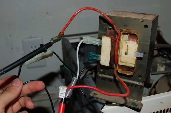
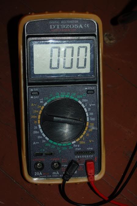
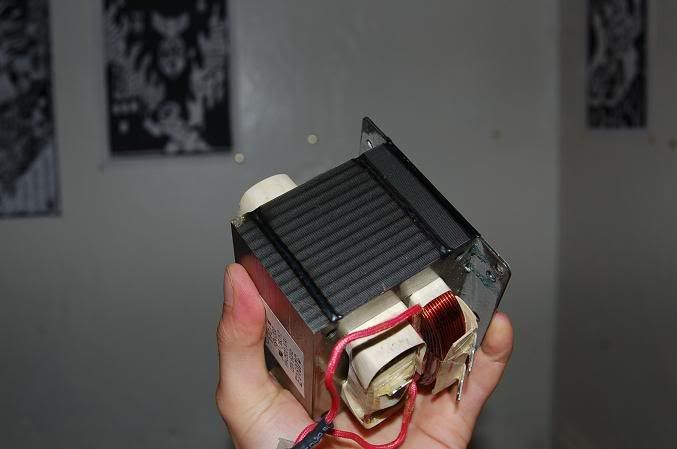
    Here's what happened (pictures below): I connected the primary to the mains, left the ground wire unattached, connected one side of the secondary to my meter, then pluged the mains cable into the wall at which point I could here a humming noise comming from within the walls seemingly (this was much louder on the smaller transformer that was in better condition). I then connected the other side of the secondary to my other probe and.... nothing? the meter just read 0. here are the pics of the setup and of my meter. Also the last pic is of the sides of the transformer which have welds all along the laminations which seems kinda strange to me, isn't the point of having laminations that they aren't connected? I planned to grind the welds off with a dremel tool. let me know if this is a crazy idea haha


  • #2
    First the warning - that innocent looking tag one the left sits at about 2500V.

    The filament winding you appear to be on should be 3 or 4 volts - check your meter/range/try a different meter, although it's likely that the transformer saturates without a load and could have blown an internal fuse with the higher current.

    Just thoughts,

    S.

    Comment


    • #3
      Does the meter still work? I bet it isn't designed for 2,500 volts.

      When testing unknown transformers, I always feed them from a variac, and start very low. The voltage ratios will be reliable, even if the absolute voltages are a fraction of normal.

      Comment


      • #4
        Is your insurance paid up? I would start with something smaller. Those microwave transformers are often in the 1000 watt ballpark. You need something that big? Laminations are welded to keep the buzzing to a minimum. Note that the 2500 volts or so output is under load. Could be considerably higher spikes when unloaded. I did something similar several (or many) decades ago when fixing a 5 kW arc lamp for exposing plates. With a Simpson 260 meter. Heard some arcing. It stopped working. Wasn't simply damaged inside. It was vaporized. Be careful. This isn't just dangerous, its lethal. Only takes microamps in the right place to stop your heart. 2kV at half an amp will surely do it.

        Comment


        • #5
          You might want to start with something easier. Try your local thrift shops for vintage stereo equiptment. I just got a free stereo console off Craiglist. I have a 12V wall wart from a thrift that I'm planning on taking apart eventually for the same reason - I'd like to rewind it to 8V output.

          Comment


          • #6
            First: MOTs are ~2200V @ 500mA, the same as an electric chair. Don't even *think* about putting your hand within a few feet of *any* wires attached to them under power (like you did in your first picture).

            Connect everything, EARTH THE CORE, and have a remote switch to powerup and view the meter. Shut off power and unplug before you twiddle with any settings.

            Seriously, you accidently brush one lead and you are DEAD in a millisecond.

            That having been said,

            You connected your DMM to the filament supply, which is only at a few volts, and your DMM set to 750V isn't sensitive enough to detect them.

            To determine the existing turns ratio in a MOT, connect mains to the secondary (smaller wire) and measure the voltage on the primary (thicker wire).

            Comment


            • #7
              Mitch,
              I have taken apart and rebuilt old PTs. I would suggest that you do not start with any that have the laminations welded together. It's just too much trouble to grind off the weld and then you end up with a bunch of messed up laminations that don't lay back together well. Surplus electronics stores and ham fests are good sources for used PTs. Sometimes you find transformers by themselves. Other times you can salvage them from old equipment that you buy for a couple of bucks. Much of the old equipment used really nice transformer cores with good end bells which aren't even installed on the microwave tranny.
              Regards,
              Tom

              Comment


              • #8
                Hi guys thanks for the responses,

                First I just want to get out there that I do realize that I should be doing this with a variac, and I've stopped fiddling with the stuff until I get one. I want to explain that in the first picture I did try to purposely get the empty socket in the background in the picture to show that everything is unplugged and I'm holding up the wires to try and show where everything is going. When I'm powering this stuff up, I A) and putting my hands nowhere near it (although a remote switch is a very good idea and I should do that) and B) although my hands are bare in the picture where everything is unplugged when the power goes on I've got heavy rubber electricians gloves on because I am pretty paranoid about getting electrocuted. Not sure if they'd save me from a shock, but the fact is I do know its lethal and my hands aren't going anywhere near the stuff except to connect the other probe.

                The reason I'm working with microwave PTs is because where I live there really isn't anything else, there aren't places where I can get junked stereos of any useful size. maybe I'm just not looking hard enough but anytime I see a stereo receiver or anything like that on the side of the road I always pick it up and strip it but I find they always have pretty small transformers.

                I'm building a 100W amp so I'm going to need something thats physically large enough to house the wire, I don't even know if these would be close enough judging on the size of regular guitar amp PTs.

                Grinding the welds is probably going to be huge pain but I just can't think of anything else right now. does anyone know where I can just buy laminations??

                so finally about what I can actually begin to do right here. so I'm apparently on the filament winding? I didn't think this type of PT would have a filament winding? inside the microwave these leds were connected to the big cap? I also obviously have it hooked up backwards I should run my mains into the secondary and hook my meter to the primary, but if those are the filaments then where is the secondary?

                I will connect the center tab there to the ground wire on the mains next time them. I'm assuming that was responsible for the humming noise? what is going on there?

                can anyone recommend a good way to get the laminations apart without bending them?

                Comment


                • #9
                  A transformer that large is too big for a 100W amp. In a microwave, they have forced air cooling and let things get pretty hot. But they get probably over 1000 watts out of a transformer that size. You may only want to use a third or less of the laminations.

                  Those transformers are made to power a magnetron tube, which is basically a diode. It has a directly heated filament. The anode is the metal envelope of the tube and is grounded. The cathode runs at negative 3000 volts or so. One side of the secondary is often welded directly to the transformer laminations, which are grounded. So, there may be only ONE visible connection to the HV winding. Sometimes they bring out both sides of the secondary. Since the filament is running at -3000 volts, the filament winding is very well insulated.

                  Since the transformer is so much bigger in wattage than what you need, I'd just recycle the laminations and not use any of the existing windings. The primary has too few turns and is too large a gauge for use as a little 100W or 200W transformer. Make a new bobbin that holds around a third of the existing laminations. You'll need more turns of a smaller gauge for the primary. You can count the turns if you take it apart. Or, calculate them approximately based on wire gauge and the DC resistance. I'd try 4 times the number that are there now. You'll lose a factor of 3 inductance by using a third of the lams but gain a factor of 16 by increasing the turns. Net result, about a factor of 5 more inductance which should be about right for 200 Watts or so. Just a rough guess. No guarantee it won't catch fire or throw sparks.

                  My experience is that you frequently have to destroy one or two laminations to get the thing apart. They're all lacquered together. Even if you heat it, which is nasty, they're still plenty stuck together. Once you grind off the welds, start at one end and pry one lamination loose as much as you can with a knife. Grab it with pliers and pull it out. Not easy. Once you have enough laminations pulled out, they can be separated with a knife and removed without much damage.

                  Comment


                  • #10
                    Originally posted by Just Bob View Post
                    A transformer that large is too big for a 100W amp. In a microwave, they have forced air cooling and let things get pretty hot. But they get probably over 1000 watts out of a transformer that size. You may only want to use a third or less of the laminations.

                    No guarantee it won't catch fire or throw sparks.
                    hahahaha how CAN I get a garauntee on that? really though, what should I be looking out for in terms of safety here? is it simply the gauge of wire used vs. the current and voltage draw? does the amount of iron matter?

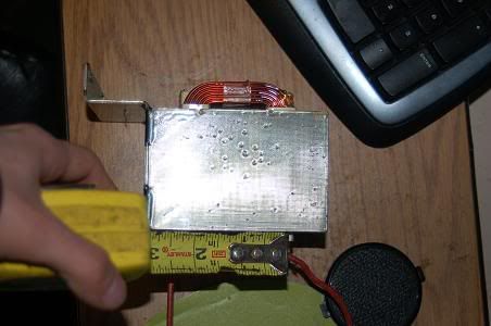
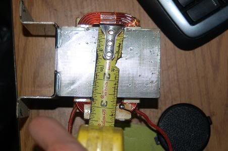
                    going back to the first thing you said about the side, every PT in a 100W amp i've ever seen has been much bigger than this thing? should i maybe put something in the picture for scale?? how do I know just how much iron i need?

                    Comment


                    • #11
                      Mitch,
                      There is a figure called "Determining cross sectional area" at the site http://geek.scorpiorising.ca/windingtransformers.html which you listed in your first post of this thread. Using that you can evaluate the power capacity of your core.
                      Tom

                      Comment


                      • #12
                        hmm I've got a question on this cross-sectional area. Why are guitar amp transformers so damn big then? the marshal major is 200 watts but I mean going but this chart the PT in the thing is big enough for 2000 watts?

                        Comment


                        • #13
                          Originally posted by MitchK View Post
                          hmm I've got a question on this cross-sectional area. Why are guitar amp transformers so damn big then? the marshal major is 200 watts but I mean going but this chart the PT in the thing is big enough for 2000 watts?
                          I'm guessing that you may be using the wrong dimentions. Are you measuring the inside core dimentions? (The part that the wire stack is wound around)
                          Or the overall dimentions of the lamination stack?
                          The former sould be used with the chart to calculate the power rating.

                          Comment


                          • #14
                            I'm measuring the part of the transformer laminations contained in within the circumference if the windings when looking at it form a side view as is in the drawing on the webpage. 1 1/2 inches by 2 1/2 inches.

                            Comment


                            • #15
                              here are some pictures


                              Comment

                              Working...
                              X