Announcement

Collapse
No announcement yet.

Pioneer DM-40 PC Speakers Repair Help

Collapse
X
 
  • Filter
  • Time
  • Show
Clear All
new posts

  • Pioneer DM-40 PC Speakers Repair Help

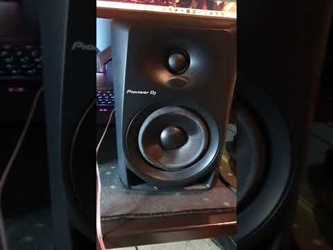
    Hi, I have Pioneer DM-40 PC Speakers that are in need of repair. I used them on a system that had an internal amp and later found out not to do that as there is one already in the speaker. When i plug it into the PC and turn it on it makes a very loud buzzing noise and pushes the cone out. No audio will play. If i have both speakers connected the right speaker had the loud buzzing and the cone get physically hot after a little while. If i only have the left plugged in it isnt as loud but still buzzes. The left speaker connects the 2 speakers together, connects to the PC and power. The Right speaker only has the connection going to the other speaker. I have included some video of the issue and photos of the speakers. If you need anything else let me know.

    I have some soldering experience (But limited component knowledge) and want to try and repair it myself if possible. I will be greatly appreciated for any help offered.

    Click image for larger version

Name:	20211201_231815.jpg
Views:	1939
Size:	2.85 MB
ID:	946196 Click image for larger version

Name:	20211201_231909.jpg
Views:	1891
Size:	2.05 MB
ID:	946197 Click image for larger version

Name:	20211201_232034.jpg
Views:	1876
Size:	3.42 MB
ID:	946198 Click image for larger version

Name:	20211201_232212.jpg
Views:	1849
Size:	2.60 MB
ID:	946199
    Attached Files

  • #2
    If the cone is moved to it full excursion as it makes a noise then you have DC on the speaker.
    The amplifier has failed.
    Without access to service information, you may be wasting your time.
    Take it to an authorised Pioneer service centre for repair.

    I would suspect the output IC and/or power supply.
    Support for Fender, Laney, Marshall, Mesa, VOX and many more. https://jonsnell.co.uk
    If you can't fix it, I probably can.

    Comment


    • #3
      Feeding one amp output into the input of another is likely to have caused multiple faults. I agree with Jon, the symptoms described are of a power amp module failure, but there's the rest of the signal path to consider, as well as a cooked speaker voice coil which could shorten its life (if not already permanently damaged) If you really do want to troubleshoot the amp yourself, then the starting point is to get a schematic and post it here. Do not continue to run the amp - you'll create more damage. Note, **shock hazard** this unit uses a switching power supply and this is not safe to work on due to mains voltage being present where you may not expect it. It's also rectified, so you have around 325v on the primary side.

      Comment


      • #4
        Idk if it changes anything but when I connected it to the other system, i only connected it through the speaker wires, Not the mains power.

        Comment


        • #5
          No offense intended, but this unit has 1) a switch mode power supply, 2) SMD components, and 3) a double sided board with through holes. If you have little troubleshooting experience and only limited soldering skills and equipment, I would not recommend attempting to repair this unit. It's highly likely you'd only make things worse.
          "I took a photo of my ohm meter... It didn't help." Enzo 8/20/22

          Comment


          • #6
            I have done a basic soldering course which was SMD work so im confident in that. I just need help diagnosing the cause of the problem and how to fix.

            Comment


            • #7
              Ok. Since you have no schematic, I would find the datasheet for the output IC. You may at least be able to determine if the IC is bad. Can you tell us the part number on the output device?
              "I took a photo of my ohm meter... It didn't help." Enzo 8/20/22

              Comment


              • #8
                This is the part im not sure about. Not sure on terminology and part ID. Are you referring to the part screwed into the heatsink at the top of one of the photos(Half visible)?

                Comment


                • #9
                  Yes, most likely. If you can tell us the part number, we can find out.
                  "I took a photo of my ohm meter... It didn't help." Enzo 8/20/22

                  Comment


                  • #10
                    Ok it has 3 lines of numbers. First is TDA7265. 2nd is CZ003934. 3rd is V6 CZ MAR. I do appreciate your help.

                    Comment


                    • #11
                      The part number is a TDA7265. It is a stereo amp and the link below is for the datasheet. I'll also attach the internal schematic/typical circuit only for easier reference.

                      1) Unhook all speakers from the amp board and leave them unhooked until you are sure the amp is not outputting DC.
                      2) Check the supply pins 3 & 6 and make sure they are equal and opposite polarity. Max value is 25V according to datasheet. The important thing is that they are at least somewhat closely matched.
                      3) Check that there is no DC on either output (pins 2 & 4).
                      4) Be careful that you don't short pins together with meter probes when testing. Report back with what you find.

                      https://www.digikey.com/htmldatashee...SAAEgKV1PD_BwE

                      Click image for larger version  Name:	TDA7265 Schematic.jpg Views:	0 Size:	114.6 KB ID:	946247
                      Last edited by The Dude; 12-02-2021, 03:27 AM.
                      "I took a photo of my ohm meter... It didn't help." Enzo 8/20/22

                      Comment


                      • #12
                        I have unplugged everything but not sure which pin is which. Also would i test it for continuity? I have included a photo.

                        https://imgur.com/a/ginkzLl

                        Comment


                        • #13
                          Sorry i didnt realise there was more to the link. I understand from the photo further down. Do i test continuity with it?

                          Comment


                          • #14
                            Buy one NOW or youŽll have to wait ONE YEAR

                            https://www.mouser.com/ProductDetail...F0pt42lA%3D%3D

                            SERIOUS.
                            Juan Manuel Fahey

                            Comment


                            • #15
                              Originally posted by KnightRyda View Post
                              Idk if it changes anything but when I connected it to the other system, i only connected it through the speaker wires, Not the mains power.
                              The amplifier is designed to accept an input of millivolts. Connecting it to another amplifier via that amp's speaker wires would put several volts on the input - way beyond the design criteria and a damaging level. The mains referred to is the mains that's on the power supply board. With an older style 'linear' power supply the mains is first fed to a transformer and then rectified and smoothed. With that type of power supply there's usually a clear identification of any components that are on the mains side. Everything else on the secondary side is low-voltage and isolated.

                              The switching power supply which is fitted to your amp is different; The mains is rectified and then switched at high frequency, so there are many more components that have high voltages present. Also under certain fault conditions, that large reservoir capacitor on the board can hold a voltage after the power is removed. The danger in working on a switched power supply is that even components that appear to carry a low voltage on the primary side are referenced to the incoming mains and are a shock hazard. You have to take special precautions when working on this kind of supply and use a current limiter and isolating transformer.

                              My advice is to steer clear of that board and take any voltage measurements on the amplifier board where the voltages are low and isolated.

                              Comment

                              Working...
                              X