Ad Widget

Collapse

Announcement

Collapse
No announcement yet.

Question about Pentode reverb drive circuit

Collapse
X
 
  • Filter
  • Time
  • Show
Clear All
new posts

  • Question about Pentode reverb drive circuit

    I'm working on a silvertone 1474 for a buddy of mine right now. One of the things we were talking about was that he took out the reverb unit because he didn't like it and doesn't use it. So there's an entire 6CG7 envelope not being used in the amplifier. This inspired me do something I've been wanting to do for a little while, which is design a ground up small signal pentode stage and a reverb drive circuit. This allows me to do both at once.
    I first learned about this idea from the article I read here:
    http://www.channelroadamps.com/articles/reverb_driver/
    For the purposes of maintenance and efficiency, I limited the design around choosing from 9-pin pentode/triode tubes with 6V heaters that are in current production. I found datasheets for the following tubes:
    6AW8A, 6AN8, 6GH8, 6BM8, and 6U8A. I chose a the 6U8A because it had plenty of current drive available for the tank I wanted to use, it was readily available, and the triode component had a little more gain available than some of the others for the recovery stage.
    Here are the mutual characteristic curves, (the first showing plate curves with a screen voltage of 110V)
    Click image for larger version

Name:	6U8A Plate Curves Vg2-110V.jpg
Views:	1
Size:	824.8 KB
ID:	873888
    The tank I'm going to use is:
    MOD 9EB3C1B
    3-spring long decay • Input Impedance 800 Ohms, Output Impedance 2575 Ohms
    Input Insulated/Output Grounded
    Horizontal, Open Side Down Mounting Plane

    Accutronics states that the nominal drive current for this input transducer as 3.1mA (just under 4.4mA peak). So, here's my question:
    To limit the drive current from overloading and saturating the input coil, I was going to set the OVg1 plate current by adjusting the screen voltage so that the current through the load doesn't exceed the 4.4mA peak to peak from it's bias point. Correct?
    For example, of one of the options I was considering. The existing circuit gives me supply voltage of 240V. With a screen voltage of around 80V, the plate current stays pretty constant until slope of the knee at around 11.5mA at OVg1. With a load of 22K and a bias of -1.5V, the output signal looks pretty linear with an input up to 2V P-P and a headroom of 3V P-P.
    The quiescent current should be around 5.2mA and should max out to 8.2mA. With a driving source impedance of 22k and plenty of signal swing drive the coil at any frequency of interest, this is enough to approximate a constant current source, correct? did I miss anything or make any mistakes? (See load line and curves for 80V screen voltage below)
    Click image for larger version

Name:	6U8A Plate Curves Vg2-80V.jpg
Views:	1
Size:	789.7 KB
ID:	873889
    If I have a 50% chance of guessing the right answer, I guess wrong 80% of the time.

  • #2
    If I understand you correctly, you want to build a driver like channelroadamps with lower current. Possibly a 22K plate resistor, although the DC load line that you drew indicates a 24.2K plate resistor. In any event, it looks like you want the plate voltage to be 116V with a current of 5.2mA when the bias is -1.5V.

    The alleged saturation current is 4.4mA peak, not 4.4mA peak to peak.

    The DC load line is only useful in determining an operating point, and you don't really even need it for that. What we need is the collection of AC load lines for all of the frequencies we are going to use. The impedance of a 1.0uF capacitor in series with a 127.3mH coil is 1.875K at 82Hz and 3.16K at 4KHz. The impedance is practically nothing at the resonant frequency of 446HZ. Numbers like these will give you an AC load line that is nearly vertical and given the low slope of the characteristic lines, vertical will work just fine.

    The published saturation current is significantly lower than the actual saturation current. I would rather exceed the saturation current than to clip the driver, so I try to have drivers that will do at least twice the saturation current.

    Comment


    • #3
      The direct drivers like the channelroadamps one have a problem around the resonant frequency. The signal gets real ugly and the reverb doesn't sound good. In actual practice, there is usually so much stuff going on with the guitar signal that this phenomenon goes unnoticed. If you put a 470r resistor in series with the capacitor and coil, the total impedance of the combination at a given frequency doesn't change much, but it never drops below 470r at any frequency. The current delivered to the coil is essentially the same with no ugliness around the resonant frequency.

      Comment


      • #4
        Originally posted by 66 Kicks View Post
        The direct drivers like the channelroadamps one have a problem around the resonant frequency. The signal gets real ugly and the reverb doesn't sound good. In actual practice, there is usually so much stuff going on with the guitar signal that this phenomenon goes unnoticed. If you put a 470r resistor in series with the capacitor and coil, the total impedance of the combination at a given frequency doesn't change much, but it never drops below 470r at any frequency. The current delivered to the coil is essentially the same with no ugliness around the resonant frequency.
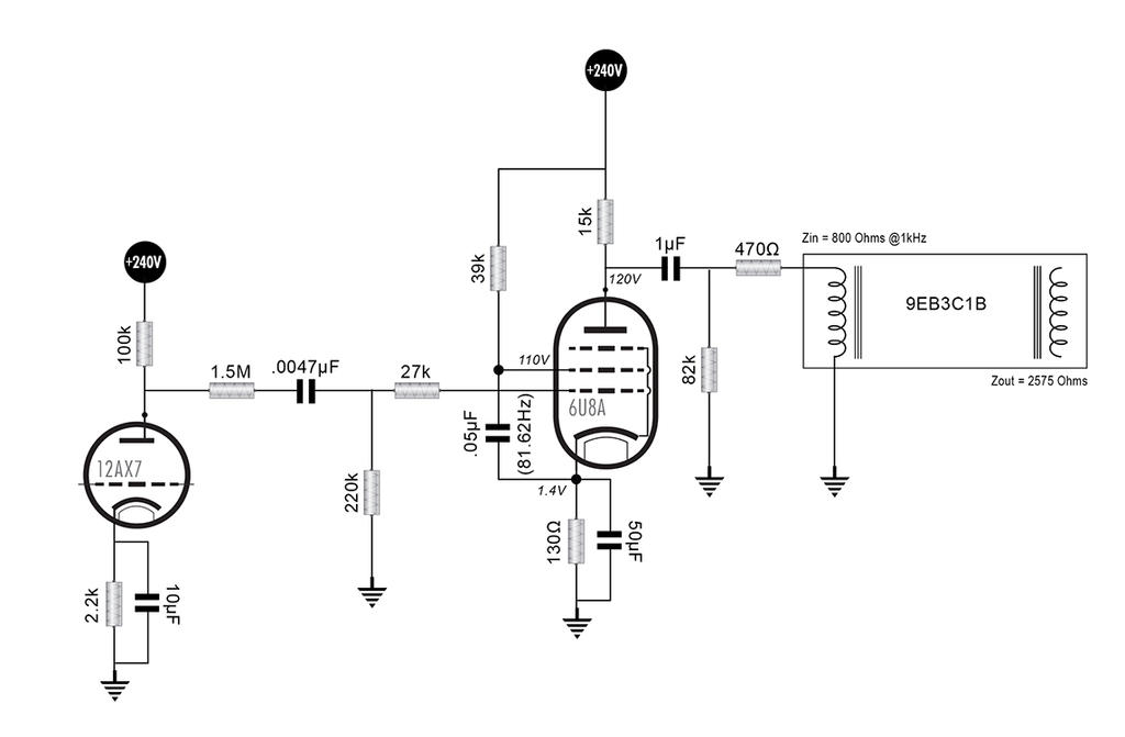
        Thank you for the corrections and response. Sorry about the mistake on the load line, I had different DC operating conditions for different screen voltages saved on different layers and that was an error of version control. Anyways, your point about giving the driving stage plenty of headroom is a good one and I had set the screen voltage too conservatively probably. I made some adjustments and drew a schematic. The 12AX7 is basically the input stage of channel 2 in this amp.


        edit: I changed the input divider of the pentode to roll off just under 10kHz
        Last edited by SoulFetish; 08-18-2018, 04:28 AM.
        If I have a 50% chance of guessing the right answer, I guess wrong 80% of the time.

        Comment


        • #5
          Originally posted by SoulFetish View Post
          edit: I changed the input divider of the pentode to roll off just under 10kHz
          That's an incredibly well designed driver, but I still have a couple of questions.

          How did you come up with the 10KHz roll off? It sort of implies a total input capacitance of 10.6pF on the pentode, but the data sheet says 5pF (Miller capacitance is negligible).

          What is the 83.5Hz by the .056uF capacitor?

          Comment


          • #6
            Originally posted by 66 Kicks View Post
            The published saturation current is significantly lower than the actual saturation current. I would rather exceed the saturation current than to clip the driver, so I try to have drivers that will do at least twice the saturation current.
            I did some experiments a while back. I drove the coil with variable currents while monitoring the distortion out the far end using an FFT on the scope. I went all the way to 20X the nominal current before seeing any change (IIRC it doubled). OTOH, there was significant movement of the springs and therefore I suspect the first limit is mechanical and not magnetic saturation. The air gap is huge and that will keep the flux down and so avoid saturation.

            This I would have no problem driving at 5-10X the nominal. Good for s/n ratio as hum pickup can be troublesome in these critters.
            Experience is something you get, just after you really needed it.

            Comment


            • #7
              Originally posted by nickb View Post
              I did some experiments a while back. I drove the coil with variable currents while monitoring the distortion out the far end using an FFT on the scope. I went all the way to 20X the nominal current before seeing any change (IIRC it doubled). OTOH, there was significant movement of the springs and therefore I suspect the first limit is mechanical and not magnetic saturation. The air gap is huge and that will keep the flux down and so avoid saturation.

              This I would have no problem driving at 5-10X the nominal. Good for s/n ratio as hum pickup can be troublesome in these critters.
              Saturation or otherwise, the input signal gets warped when enough current is ran through the input coil. A sine wave driving the tank sounds much more pleasant than a warped signal driving it.

              An 8 Ohm tank can take six times the nominal current before it warps the signal, but an 800 Ohm tank only needs twice the nominal current to warp. That would seem to argue against saturation as the cause since both have the same Amps Turns number.

              Comment


              • #8
                Originally posted by 66 Kicks View Post
                That's an incredibly well designed driver, but I still have a couple of questions.
                Thank you. I appreciate your input on this. I'm trying to correct any mistakes I might be making.

                How did you come up with the 10KHz roll off? It sort of implies a total input capacitance of 10.6pF on the pentode, but the data sheet says 5pF (Miller capacitance is negligible).
                The 10.6pF was the capacitance figure I used, but it was a mistake. Thanks for catching that. I read the datasheet wrong and mistakenly added all the inter-electrode capacitance figures together as the input capacitance instead of the quoted combined grid to all other electrode capacitance.
                Click image for larger version

Name:	6U8A-TungSol.jpg
Views:	1
Size:	257.1 KB
ID:	851422

                What is the 83.5Hz by the .056uF capacitor?
                Yikes! I uploaded the wrong file. That has the wrong screen grid resistor value on it. It should read 39k, .05µF, and (81.62Hz) accordingly.
                I'll correct that now.
                I used 1/(2π*Rg2*Cg2) to calculate the cutoff frequency for the screen grid bypass capacitor
                If I have a 50% chance of guessing the right answer, I guess wrong 80% of the time.

                Comment


                • #9
                  It won't let me update the original post. So, here is a the schematic with the correct Rg2 and Cg2 values.

                  If I have a 50% chance of guessing the right answer, I guess wrong 80% of the time.

                  Comment


                  • #10
                    That Channelroads article is inspiring a few efforts around the globe.
                    Here is Aussie Grant Wills effort - for your possible interest: His schematic at post #10
                    https://www.guitargear.net.au/discus...?topic=47588.0
                    Cheers,
                    Ian

                    Comment


                    • #11
                      Originally posted by 66 Kicks View Post
                      Saturation or otherwise, the input signal gets warped when enough current is ran through the input coil. A sine wave driving the tank sounds much more pleasant than a warped signal driving it.

                      An 8 Ohm tank can take six times the nominal current before it warps the signal, but an 800 Ohm tank only needs twice the nominal current to warp. That would seem to argue against saturation as the cause since both have the same Amps Turns number.

                      Thanks for the input. I had done my testing on an 8EB2C1B previously.

                      I was keen to try reproduce your results so I did it again but using an 8AB2C1B. I saw the same behavior as the high impedance tank. The distortion gets to about 3.5% at 20x the recommended drive looking at the 2nd harmonic (which was about 14db higher than the 3rd). If you go much further to about x22 or so it goes badly wrong will all kinds of odd frequencies popping up indicating a mechanical issue. No sign of saturation.

                      Click image for larger version

Name:	8AB2C1B.JPG
Views:	1
Size:	49.2 KB
ID:	851423

                      From this I would suggest that a 5x to 10x range should be well within the tank's capability.
                      Experience is something you get, just after you really needed it.

                      Comment


                      • #12
                        Originally posted by nickb View Post
                        I had done my testing on an 8EB2C1B previously.

                        I was keen to try reproduce your results so I did it again but using an 8AB2C1B.
                        If I understand you correctly, you are driving the input coil with variable current and analyzing the signal at the output coil. I am talking about what happens to the signal at the input coil with increasing current whether the springs are intact or not.

                        Comment


                        • #13
                          Originally posted by SoulFetish View Post
                          It won't let me update the original post. So, here is a the schematic with the correct Rg2 and Cg2 values.
                          I like the first one with the 68K Rg2 better.

                          Using the graphs you posted for 110V screen, a 15K plate resistor at a -1.4 bias looks about like 122V on the plate. 240V - 122V = 118V drop across the 15K resistor which is about 7.9mA. The screen grid is drawing about 0.37 times the current of the anode, so about 2.9mA. We need to drop 130V to get the screen to 110V, so 130V/2.9mA = 45K. So a 47K screen resistor would be a good starting value. The cathode current is 7.9mA + 2.9mA = 10.8mA. We want -1.4V bias, so 1.4V/10.8mA = 130 Ohms for the cathode resistor.

                          Comment


                          • #14
                            The 68K Rg2 with the .056uF bypass capacitor works out to 41.8Hz. This is where the bass cut is almost complete, and it is a considerable cut. Just as an educated guess I would say that the bass frequencies start getting noticeably cut around 200Hz. I like it because those lower frequencies just muddy-up the reverb. For a 47K Rg2, a 0.082uF Cg2 might be a good choice.

                            I don't like high frequencies like 3KHz and above, either. If you eliminate the 27K grid stopper and put a 250pF capacitor from g1 to ground, the cut-off will be about 3.3KHz.

                            Other people may have different preferences.

                            Comment


                            • #15
                              Originally posted by 66 Kicks View Post
                              If I understand you correctly, you are driving the input coil with variable current and analyzing the signal at the output coil. I am talking about what happens to the signal at the input coil with increasing current whether the springs are intact or not.
                              Yes, that's right.

                              I re-jigged to monitor the input current over a 10 ohm resistor, which I agree is a better way to check for just saturation. I used the low impedance tank and was able to get to 26x the nominal current for the 2nd harmonic at -26db. The waveform is looked quite triangular at this point. Back off to 20x and the 2nd harmonic is -45dB and the waveform is clean, as you would expect with so little distortion.

                              I've looked at this from both sides now, as they say, and find nothing that disagrees with my original numbers.
                              Last edited by nickb; 08-21-2018, 07:06 PM.
                              Experience is something you get, just after you really needed it.

                              Comment

                              Working...
                              X