Announcement

Collapse
No announcement yet.

rebuilt my 5e3> hum issue

Collapse
X
 
  • Filter
  • Time
  • Show
Clear All
new posts

  • rebuilt my 5e3> hum issue

    havent been in the 5e3 section for a while. my 5e3 build turned to a spare parts bin after not being used due to the hum, which was too much of a hassle to fix due to my bad choice of a chassis (had a small opening, and my wires were in 3d due to the placement of the board tubes and controls all being on different faces). this made things quite difficult to do any work on it once there were many connections in there.

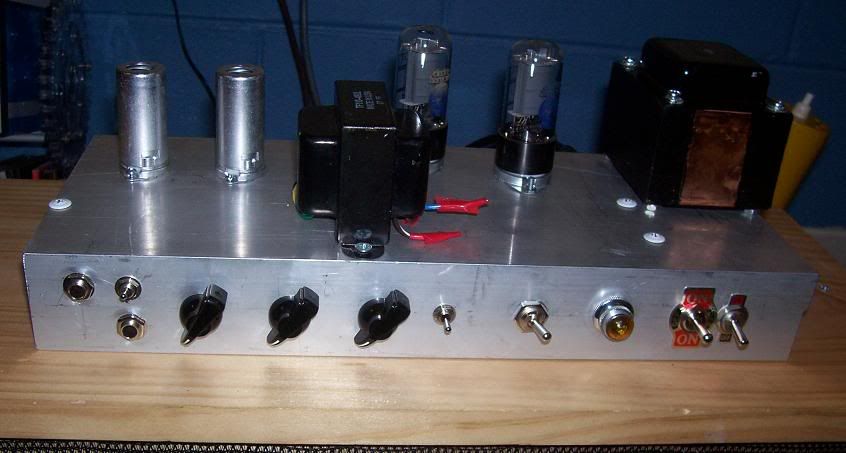
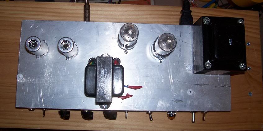
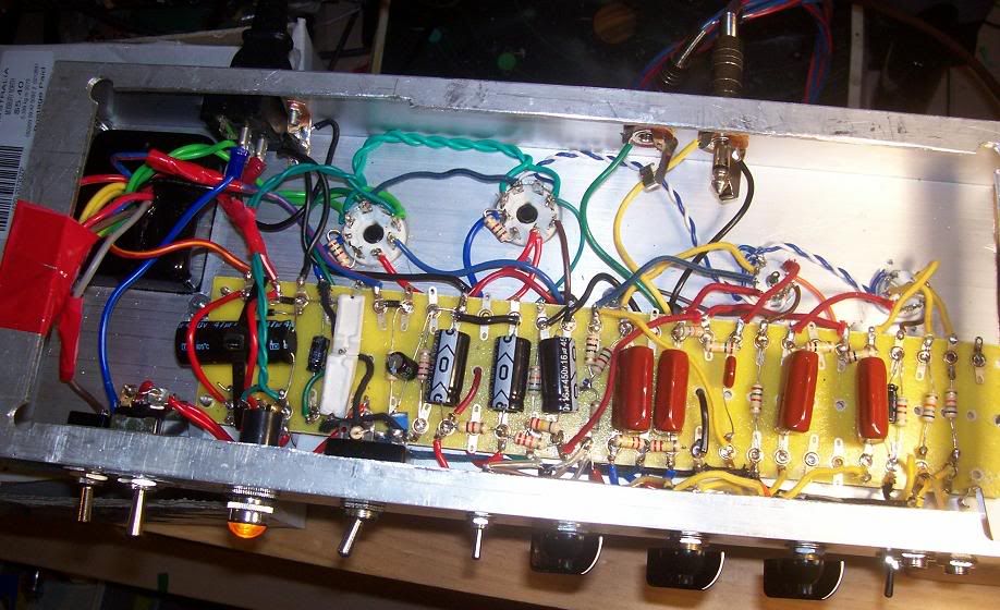
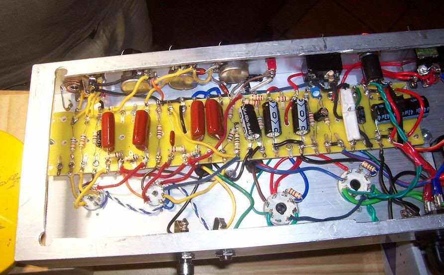
    so the other day i decided to rip out the board and all its connections, the sockets and pots and put it into a chassis made from a 150x50mm aluminium extrusion. things fit much nicer. i wired the power supply as a 300vac winding to a bridge rectifier, and then put it into a 47ohm resistor to get closer to the right voltage. there was also a 47uf cap before the 47 ohm resistor. after this it goes into the normal power supply with 16uf caps and 4k7/22k resistors. this was to get rid of much of the power supply ripple, and get some sag through the resistor. i also added a -ve voltage supply so i could put a switch in to switch it to fixed bias. i also added a voltage divider from the last preamp supply to float the heaters at ~40-60v. i only put 2 inputs (1 per channel) and put a switch to link the 2 channels at the input. theres also a switch to change the cathode bypass cap on the gain stage before the PI.

    having done a few things there that should have eliminated alot of hum i was surprised how much hum there actually was. i did a bit of reading and it seems i need to separate the filter cap ground for the preamp from the others, and i suspected having the power supply ground connected to the leg of the PT bolt could possibly effect hum. this should minimise hum for the amp.

    the main issue i have with the hum is for the bright channel. the hum is so bad that it is very unusable. i wouldnt be surprised if on full the hum started to distort. the hum comes from before the vol pot, and is alot worse than the other channel. i disconnected the lead going from the coupling cap to the vol control, and there was no hum coming from the channel. the gain stage has the stock shared 820ohm/25uf cathode bias, so its not an issue with that, otherwise it would effect both channels. the plate resistor comes from the same supply as the fender layout, so i dont see how the hum could be coming from there (im sure some does, but not the bulk of it).

    i've just got a scope, and am a still learning how to use it effectively. i am seeing some hum on the output from the coupling cap (where the lead to the vol pot would be). there is no noticeable hum on the output of the normal channel (i did turn the vol to full so that there was a full 1m resistance to ground across the pot).

    i've done a bit of chopsticking to the wires going into the tube socket, and there doesnt seem to be an audiable difference.

    does anyone have any ideas as to what the reason for so much hum on the bright channel? i will get some photos when i get home later.


    edit: i am using a split grounding circuit of some sort. i have the filter caps and the cathodes of the 6v6's connected to a copper plate that is bolted to the chassis (was connected to the PT connection bolt, but i may move that). the other connections are daisy chained together and connected to one of the input jacks. i hear that daisy chaining isnt the best way, but i've done it before without issues. the main issue i have is the inst channel issue. i want to get that right before doing the minor fixes.

  • #2
    "i hear that daisy chaining isnt the best way, but i've done it before without issues. the main issue i have is the inst channel issue. i want to get that right before doing the minor fixes." The hum is proably on both channels, just the EQ of the inst channel makes it more audible. Daisy chaining is not the best way...how long will it really take you to snip the daisy chained wires an run seperate wires to your ground points?

    Ground the preamp filter to the input jack.

    Double check for any ground loops components must be grounded at one point only.

    Comment


    • #3
      Hi black_labb

      Got any pics?
      Building a better world (one tube amp at a time)

      "I have never had to invoke a formula to fight oscillation in a guitar amp."- Enzo

      Comment


      • #4
        here are some pics.


        a few messy points near the output, partially from moving the ground location to the plug input bolt, hoping that was going to help.
        i rewired some of the grounding, with no noticeable improvement. im sure its better, but whatever is making the hum so bad is masking the minor fix. i didnt go completely star, but the daisy chains now only link a couple components (ie the vol pot's grounds, the 1st stage cathode, the 2nd stage cathode + preamp filter).

        i think you may be right mwjb, it could be the TS on the bright channel making it seem louder, as both are quite bad

        i checked for other ground links on a couple of the ground wires in the preamp when relocating them. didnt find any ground loops there. i havent been able to find any other issues thus far.

        my only 2 ideas for the issue atm are (aside from me missing a ground loop)

        1. my method of floating the heaters (a voltage divider from the preamp power supply 220k-56k to get ~45v) is inserting an ac signal into the power supply. i am quite sure the 56k from the heaters to ground is the only connection. i measured 50k from one side of the 56k to ground.

        2. the chassis is a big ground loop???? the chassis has open ends as it was cut from an extrusion, could this make it a big ground loop?

        thanks for the help guys.

        Comment


        • #5
          Daisey chaining is actually the best way but if you have a ground at the input jacks AND at a transformer bolt on the rectifier end, it's hum city. Look at the hum with your scope. Is it 50Hz or 100Hz? A 100Hz buzz comes from grounds in the power supply and rectifier circuits but a 50Hz hum can come from the heater supply and lead dress. The preamp filter cap should be grounded at one of the preamp tube's cathode resistors. Ground for the volume and tone controls should go to the 2nd stage cathode ground. A grounding plate is usually a disaster.
          WARNING! Musical Instrument amplifiers contain lethal voltages and can retain them even when unplugged. Refer service to qualified personnel.
          REMEMBER: Everybody knows that smokin' ain't allowed in school !

          Comment


          • #6
            Try either

            1) a split-ground, or

            2) maybe lifting the ground return path from the input socket ground and inserting a .01 - .1 uF cap to bridge the ground return path to the input socket ground (whilst keeping the other ground at the PT bolt). (This option was suggested to me a while back by Simcha (formerly Stephen) Delft. I have not tried it myself but it could be worth a shot)
            Building a better world (one tube amp at a time)

            "I have never had to invoke a formula to fight oscillation in a guitar amp."- Enzo

            Comment


            • #7
              Originally posted by loudthud View Post
              Daisey chaining is actually the best way but if you have a ground at the input jacks AND at a transformer bolt on the rectifier end, it's hum city. Look at the hum with your scope. Is it 50Hz or 100Hz? A 100Hz buzz comes from grounds in the power supply and rectifier circuits but a 50Hz hum can come from the heater supply and lead dress. The preamp filter cap should be grounded at one of the preamp tube's cathode resistors. Ground for the volume and tone controls should go to the 2nd stage cathode ground. A grounding plate is usually a disaster.
              are you saying that having the separate grounding points either sides of the amp is making the hum? or that if there is a ground loop its so big that it causes the hum.?

              i think the hum is coming from the power supply, as its quite bright/raspy when you turn the tone control up. will check the frequency when i have time.

              would i be better off linking the power supply grounds to the input jack as well by daisy chaining them to the preamps filter cap, and using the ground connection at the PT for mains earth only?

              i was under the impression that i was using a split ground method, by putting the ower supply and power cathode resistors to one connection, and the preamp connections to another ground connection, but obviously its not working very well.

              Comment


              • #8
                "i was under the impression that i was using a split ground method, by putting the ower supply and power cathode resistors to one connection, and the preamp connections to another ground connection, but obviously its not working very well." - You have more to worry about than grounding, your layout is not good. I would re-do the board layout, you want components to line up with the tube socket that they feed, especially with regards to grid wires, which should be short. The split ground method works perfectly when properly executed.

                Don't fret about keeping filter caps on the board, they can run from circuit direct to prescribed ground if necessary. They are taking up room on the board that could be better used by the PI circuit for instance.

                Those 68K's also, why not mount these on the jack, taking up too much real estate on the board.

                Your plate wires should not be in close proximity to grid wires, they can be long, pressed down against the chassis floor, sweep them out & round the tube sockets.

                Your dc biasing of the heaters should not be necessary in a push-pull amp, in any case you want no more than 40vdc. There should be no other ground reference for the heater circuit other than the voltage divider load resistor.

                Loudthud said, "Daisey chaining is actually the best way". I disagree, vociferously. I have reduced hum in amps on many occasions by doing away with the daisy chain and running ground wires direct from components to specified ground point.

                Comment


                • #9
                  just lost a long reply by pressing backspace only to trigger the back button and losing my work.

                  gist was that i wont be redoing the layout atm, as i feel that the issue i have is from before the vol controls, and they are only really effected by the first stage. thats not to say that its not good advice, but i think the more serious issue is the grounding at the input.
                  i may however move the 68k resistors off the board and move the coupling caps across a bit. i would shield the input wires if this is the case. i think the issue i had was that i was using the input jack ground for the ground point (the bright channel, which was the worst offender). i will do a new ground point near the preamp filter cap, so that the grounding currents dont flow into the preamp jack. i will leave the jacks grounded to the chassis, but i may try isolating them if hum before the vol pots is still an issue.

                  the last amp i did was an 80ishw amp which i used tagstrips either side of the tubes, which made the wire runs very short and i ended up with a very quiet amp guess i was pretty lucky to get by with little knowledge. guess its time to learn the details about grounding.
                  if i did redo the amp i would use tagstrips again, only reason i didnt was because i had a fully populated tagboard. i find they make it cleaner and easier to work on, only issue is the aesthetics look a bit cluttered, but it works very well. if i do, i'll need to get some different screws, as the small sheet metal screws dont like going very far into the 3mm aluminium, might just need to use the next size drill sbit though.

                  thanks for the help everyone, i'll post my findings when i finish the rewiring of the grounds and improve the heaters.

                  Comment


                  • #10
                    "i'll post my findings when i finish the rewiring of the grounds and improve the heaters." ...and those plate wires (pins 1 & 6 12AX7).

                    Comment


                    • #11
                      Hey black labb

                      Where does the CT of the PT's HV winding connect to? This is the most important ground node in the amp. It should connect directly to the (-) terminal of the first filter cap, and shouldn't be used as a ground bus for anything else. So, HV CT to filter cap negative, and then filter cap negative to the rest of your ground system.
                      "Enzo, I see that you replied parasitic oscillations. Is that a hypothesis? Or is that your amazing metal band I should check out?"

                      Comment


                      • #12
                        Originally posted by MWJB View Post
                        "i was under the impression that i was using a split ground method, by putting the ower supply and power cathode resistors to one connection, and the preamp connections to another ground connection, but obviously its not working very well." - You have more to worry about than grounding, your layout is not good. I would re-do the board layout, you want components to line up with the tube socket that they feed, especially with regards to grid wires, which should be short. The split ground method works perfectly when properly executed.

                        Don't fret about keeping filter caps on the board, they can run from circuit direct to prescribed ground if necessary. They are taking up room on the board that could be better used by the PI circuit for instance.

                        Those 68K's also, why not mount these on the jack, taking up too much real estate on the board.

                        Your plate wires should not be in close proximity to grid wires, they can be long, pressed down against the chassis floor, sweep them out & round the tube sockets.

                        Your dc biasing of the heaters should not be necessary in a push-pull amp, in any case you want no more than 40vdc. There should be no other ground reference for the heater circuit other than the voltage divider load resistor.

                        Loudthud said, "Daisey chaining is actually the best way". I disagree, vociferously. I have reduced hum in amps on many occasions by doing away with the daisy chain and running ground wires direct from components to specified ground point.
                        there isn't any inherent problem that comes from daisy chaining points. Just depends on how you connect ground points together. Starred points, a plane (like the brass plate), and daisy-chained (series connected) points can be equivalent.

                        Comment


                        • #13
                          Steve, he said he wired it for a bridge rectifier - I read that as no center tap.
                          Education is what you're left with after you have forgotten what you have learned.

                          Comment


                          • #14
                            im going to redo alot of the layout of the tagboard. i started taking things out and shuffling them around, and also will be using a larger HT tap, as the current tap is giving me 340-350v at the output from the rectifier, which is too low if i want to use a sag resistor. i'm going to try the 0-370v tap (300 was what i was using before) and i'm going to use a 340ohm resistance, and switch a second resistor in parrallel if i want higher voltages.

                            i may put a single tag strip in to mount the coupling caps that go to the power tube grids.

                            Comment


                            • #15
                              Oh, I never noticed it was a bridge rectifier. What I said still stands, substitute "negative terminal of the bridge rectifier" for "PT center tap".
                              "Enzo, I see that you replied parasitic oscillations. Is that a hypothesis? Or is that your amazing metal band I should check out?"

                              Comment

                              Working...
                              X