 Tweet
Tweet
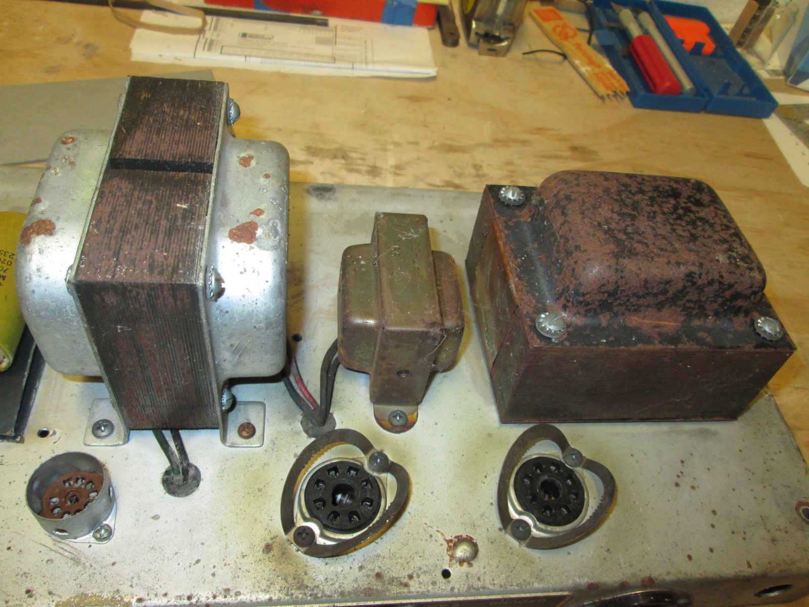
Here is a before shot of the chassis from the black lagoon.

-
It's weird, because it WAS working fine..... -
And here is the chassis , bell covers and 'custom' black choke after rust removal and paint.
It's weird, because it WAS working fine.....Comment
-
"If that's where the Bassman was mixing its channels before, it'll do fine for your modded channel. You needn't add a cathode driver for the EQ stack, just swap out the existing caps for a couple 0.022's, a 33K or 56K slope resistor, and 500 pF or 1000 pF treble cap. Replace the 8200R with a 25K pot for midrange & there you go."
Leo what is your take on the 500 pF or 1000 pF treble cap vs. the 250 (0.00025) cap on the 5F6-A schematic?It's weird, because it WAS working fine.....Comment
-
As you increase the value of the treble cap, you lower the corner frequency at which the treble "filter" operates. Go big enough and you start to bring in more mid frequencies. Could describe it as, the higher the cap value, the more aggressive the treble control becomes. And you can pick an intermediate value, whatever pleases your ears. Or use a switch to select a variety of values. It's all been done before & you can too.Originally posted by Randall View PostThis isn't the future I signed up for.Comment
-
Would a 51v cap be OK?Originally posted by Randall View Post The only good solid state amp is a dead solid state amp. Unless it sounds really good, then its OK.
Comment
-
Actually a 50v cap in a 50v circuit would be fine. E-caps are rated for "working voltage", meaning a 400 WV cap is fine in a 400v circuit. They also have a surge rating which is a higher voltage. That covers things like power up when the tubes are not warm and the B+ goes high.
What I see as a problem is where Fender specifies a 50v cap in a circuit delivering -55v to the tubes. Both numbers printed on the same schematic.Education is what you're left with after you have forgotten what you have learned.Comment
-
It's -45v on my print.It's weird, because it WAS working fine.....Comment
-
I don't recall the specific model with the "upside down" spec, I wasn't referring to your amp in particular.Education is what you're left with after you have forgotten what you have learned.Comment
-
Well, we're getting there. Sockets and filament wiring are in, brass control plate almost filled in, board mostly done, filter board almost done. I wised up on this build and will mount the transformers and AC cord last, makes flipping the chassis over and over to get to the other stuff much easier. Waiting on a few resistor values, and then the rest gets wired.
It's weird, because it WAS working fine.....Comment
-
Beauty of a build! Mind if I ask what gauge and type (stranded, solid etc) wire you used for your heater wiring, and if you used the same gauge all across?The only good solid state amp is a dead solid state amp. Unless it sounds really good, then its OK.Comment
-
I use green 18 ga. solid cloth covered for filaments and grounds, and 22 ga. solid cloth covered for everything else. I use red for HV and preamp plates, yellow for grids and tone controls, blue for cathodes, etc. I like it better than the standard Fender all yellow wiring. Also, grey fiber board, no more black for me!It's weird, because it WAS working fine.....Comment
-
Thanks Randall!Originally posted by Randall View PostThe only good solid state amp is a dead solid state amp. Unless it sounds really good, then its OK.Comment
-
That is one hefty set of transformers!Originally posted by Randall View PostThe only good solid state amp is a dead solid state amp. Unless it sounds really good, then its OK.Comment
-
Good point.
Randall: You sure that ain't a Twin Reverb OT? My Bassman came with one...
Mike: You should see a Bassman 100 OT!
Justin"Wow it's red! That doesn't look like the standard Marshall red. It's more like hooker lipstick/clown nose/poodle pecker red." - Chuck H. -
"Of course that means playing **LOUD** , best but useless solution to modern sissy snowflake players." - J.M. Fahey -
"All I ever managed to do with that amp was... kill small rodents within a 50 yard radius of my practice building." - Tone Meister -Comment
-
soldering stuff that's broken, breaking stuff that works, Yeah!Comment
Comment