Hey guys, I also spoted that thing, I've two different value for that cap either 470p or 4n7. Since we sold the last one from the shop where I work, I can't check inside the chassis... Could anyone give me the right value?
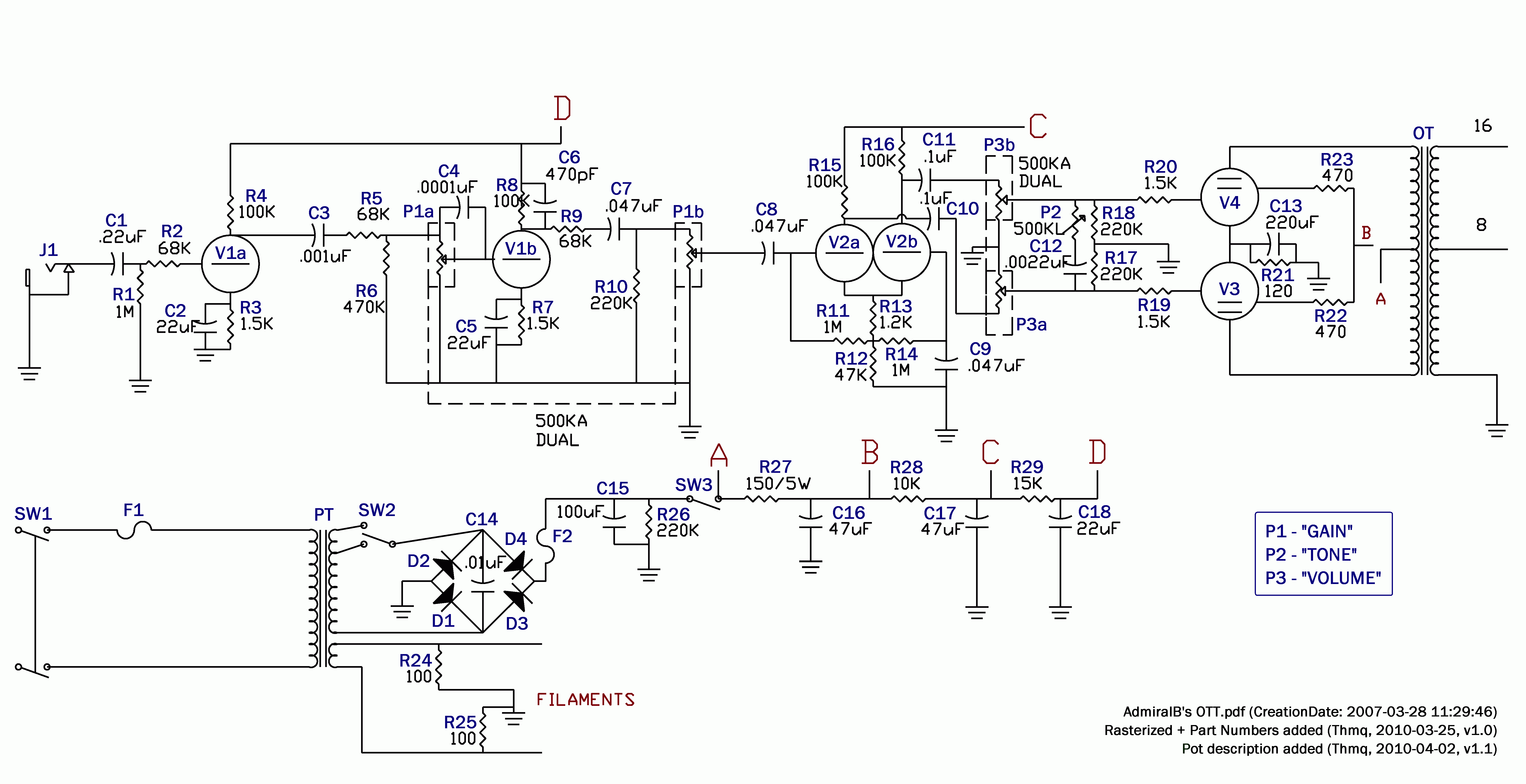
I have created 100% part-numbered version of AdmiralB's schemo so we can discuss this schemo easier in the future.
Beware: part numbers are completely "artificial", they do not match with original numbering or numbering of any other OTT schemo around. If you refer this numbering, declare so (as you should do if referring any other source as well btw. ), preferably by linking this schemo.
I had to turn original vector image into bitmap as I had no tools to edit original picture. For printing use hi-res (600DPI) version: AdmiralBs_OTT_w_PNs_600DPI.png
Cheers, T.
PS: dnpqkc, djib bed'o - I'll try to answer later, I'm bit short of time now..
I m looking to get the value of C18, is it 4n7 or 470p???
cheers everyone
Hi, it's 470pF, I'm 99% sure:
4n7 would be "insane" big, cutting to much from the signal and would lead to muddy sound.
I've seen this value only on derivates of original AdmiralB's schematic and these derivates usually contain few inaccuracies (AdmiralB stated IMO from the beginning this value as 470p /0.00047 in older version of his OTT.pdf IIRC/)
Btw. you can find some discussion about this part in this thread already (you may be interested).
I am looking at admiral's schematic for this. Does anyone know which caps or resistors to toy with to get a little more highs out of this thing? I am also experiencing the "honky" sound. Needs to be a little brighter.
You can start by lowering value (or removing) of C6 which forms low-pass filter (with output impedance of V1b stage).
If you would not mind to loose little bit of overall gain, you can also lower value of C5 to value which would boost only high frequencies (something like 47n-220n foil cap..?).
Next possibility would be to try to add "bright" cap to second part of gain pot (P1b) analogically to P1a+C4.
There are other possibilities for sure.
Just be careful, boosting high frequencies may lead to oscillations.
Is the 500KL between P2 and C12 the tone pot? If so, would changing the values of c12 or c13 also affect the highs?
I am very new at all of this so please correct me if I am wrong. The tone pot works by attenuating high frequencies. The point where it starts to roll off the frequency may be say 10khz (just for the sake of argument). Now if I want to it to control more highs, then we would say I actually want to lower that point to say (for example) 5khz so that I would be controlling the attenuation of a broader frequency range...Is this correct?
I just acquired a TT that had apparently been in a car crash -- free. Not much damage at all but the OT is kinda bent. The chassis and the pcb are unharmed and I checked out the PT last night -- good... I may end up with a TT for just a couple bucks.
I'd like to build a couple of clones myself. Are there any opinions if building this circuit on a traditional Fender tweed style circuit board would impact performance. I like the simplicity of making a board like this using turrets on each side with the components in the middle.
Yea, I know it sounds like a dumb question but its more along the lines of whether or not the PCB configuration provides any value for noise isolation or maybe the locations of the transformers are unique...
Yea, its a dumb question I suppose. I just don't want to fully copy the existing pcb 'cuz that sorta really crosses the line for me.
Am I correct in figuring that a 150ma PT is adequate. EL84s: no more than 46ma each; and the AX7s no more than 10ma each? Its been over a year since I went shopping for transformers but I think I found a close enough PT at WeberVST.
I just acquired a TT that had apparently been in a car crash -- free. Not much damage at all but the OT is kinda bent. The chassis and the pcb are unharmed and I checked out the PT last night -- good... I may end up with a TT for just a couple bucks.
I'd like to build a couple of clones myself. Are there any opinions if building this circuit on a traditional Fender tweed style circuit board would impact performance. I like the simplicity of making a board like this using turrets on each side with the components in the middle.
Hi Mark!
Good luck with the repair of crashed TT!
I believe that you can use any of usual tube-amp-building approaches to build TT clone (PCB, point-to-point..) keeping usual rules for building high-voltage and high-sensitivity circuit, TT is not IMO special case from this point-of-view. Go thru whole this thread, you can find useful hints here.
Am I correct in figuring that a 150ma PT is adequate. EL84s: no more than 46ma each; and the AX7s no more than 10ma each? Its been over a year since I went shopping for transformers but I think I found a close enough PT at WeberVST.
Yes, I believe that 150mA PT is adequate, but maybe go for second opinion yet.
Maybe link to exact PT you have chosen (if possible), it could help.
Is the 500KL between P2 and C12 the tone pot? If so, would changing the values of c12 or c13 also affect the highs?
I am very new at all of this so please correct me if I am wrong. The tone pot works by attenuating high frequencies. The point where it starts to roll off the frequency may be say 10khz (just for the sake of argument). Now if I want to it to control more highs, then we would say I actually want to lower that point to say (for example) 5khz so that I would be controlling the attenuation of a broader frequency range...Is this correct?
I appreciate any help.
DP
Hi David, you have probably moved further meanwhile, but I'll try to answer anyway, at least for the record
Yes, P2 is the Tone pot (good point btw., thanks, I did updated schemo to contain pots description (v1.1)).
Yes, changing of C12 would affect roll-off frequency of tone cut filter, but I'm not sure it is what you are looking for (IMO it won't move you to the point where sound would be brighter compared to the stock values). Here I would strongly advice to try simulation - I use free LT Spice IV simulator, great tool!! There are lot of tutorials how to use it, e.g. you can try to start here: LTSpice AC Analysis with the BMP Tone Stack by gaussmarkov
C13 is analogical to C5, but at "MASTER VOLUME" level - stock value boosts full spectrum, lowering of this value would lead to boost of high frequencies only, but you would loose some of overal volume this way.
Q: Do the secondary voltages drop by half if I use the 240 primary and connect to 120VAC outlet? If this is the case, I can look at a lot more PTs.
Yes, including the heater voltage, which makes it a bit pointless. The VA rating is also halved.
Surely a PT for an 18 watt Marshall type amp would do. Something like the Hammond 261G6 or 261M6. That Weber one is too big.
The lower voltage tap is just for the power reduction feature, you don't absolutely need it. Also you could use a full wave rectifier instead of a bridge, and use any 18 watt clone PT that way.
"Enzo, I see that you replied parasitic oscillations. Is that a hypothesis? Or is that your amazing metal band I should check out?"
Well, you still may consider using 220V primary for 120V mains and for filaments use 6.3V and 5V secondary windings in series - it should give you 6.2V/3A ((6.3+5)*120/220), which could do the job.. but I'd definitely search for more suitable PT first
 Tweet
Tweet
 ), preferably by linking this schemo.
Comment