Ad Widget

Collapse

Announcement

Collapse
No announcement yet.

Anyone know what the "tiny terror" circuit is?

Collapse
X
 
  • Filter
  • Time
  • Show
Clear All
new posts

  • Originally posted by djib bed'o View Post
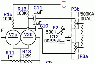
    the tone control should be in between C 10 and C 11 and the outs going to R17, 18, 19 and 20...
    Do you mean like this:


    ?

    I did implement it this way too, it seemed more logical to me and it works well.

    I wonder if AdmiralB's scheme is correct at this point, but I cannot check it, I don't have access to original OTT..

    T.
    Last edited by Thomeeque; 04-09-2010, 11:56 AM.

    Comment


    • Hello,
      I'm building a Tiny Terror of my own and using this thread to help me. I have a few questions that need answering:

      I've got 2x 1MOhm Stereo log potentiometers, is there any way for me to use them for the volume and gain knobs, can I just use them as is or could I perhaps connect a resistor to them to use them?

      I've got a PT with 250VAC out and two taps, 210VAC and 164VAC, which one should I use for the low power switch tap?

      Why is the capacitor in the capacitor in the rectifier bridge connected to the AC inputs? I've been told this is for some regulation

      What are the specifications of the fuses?

      How are the valve heaters connected? ( I bet I can figure this out with the datasheets tho' )

      That's all the questions I remember for now

      Any help whould be wonderful!
      Thank you
      Ragnar
      Last edited by RagnarArdal; 04-19-2010, 11:19 PM.

      Comment


      • I will be soldering my terror this weekend, some feedback whould be much appreciated!

        Comment


        • Which components are V5 and V6?

          Hi, this is my first post (i'm sorry for my english )
          Which component are V5 and V6?
          plese, excuse my ignorance

          Comment


          • Originally posted by RagnarArdal View Post
            Hello,
            I'm building a Tiny Terror of my own and using this thread to help me. I have a few questions that need answering:
            Hi Ragnar!

            I'm sorry, I have somehow missed your post(s) - did you already started? How it's going?

            I'll refer this schemo:

            Originally posted by RagnarArdal View Post
            I've got 2x 1MOhm Stereo log potentiometers, is there any way for me to use them for the volume and gain knobs, can I just use them as is or could I perhaps connect a resistor to them to use them?
            I would personally save these for another build and buy proper values, but yes, I'd say that you can use them:

            For gain pot P1a + P1b I would probably try to achieve same load for preceding stages (made by parallel combinations R6||P1a and R10||P1b) as in original OTT, as this may influence characteristics of the preamp section. I would either adjust R6 & R10 values:

            R6: 470k => 330k (470||500 = 242 ~ 330||1000 = 248)
            R10: 220k => 180k (220||500 = 153 ~ 180||1000 = 153)

            or add another 1M resistor in parallel.

            For volume pot P3a + P3b I would maybe try to just simply use 1M pot without any adjustments.

            Originally posted by RagnarArdal View Post
            I've got a PT with 250VAC out and two taps, 210VAC and 164VAC, which one should I use for the low power switch tap?
            Original is around 180VAC IIRC, so I'd use those 164VAC. It should be still in usable area with just slightly lower power, which is IMO good thing

            Originally posted by RagnarArdal View Post
            Why is the capacitor in the capacitor in the rectifier bridge connected to the AC inputs? I've been told this is for some regulation
            I believe it filters out some peaks caused by diode switching or something like that, but I don't know really If you are really curious do deeper study or try to emulate it (e.g. by LTspice).

            Originally posted by RagnarArdal View Post
            What are the specifications of the fuses?
            I have used:

            F1 = T315mA Slow Blow
            F2 = T250mA Slow Blow
            Fheaters = T6.3A Slow Blow (not on schemo)

            Originally posted by RagnarArdal View Post
            Hello,
            How are the valve heaters connected? ( I bet I can figure this out with the datasheets tho' )
            All in parallel - yep, check datasheets for details..

            Originally posted by RagnarArdal View Post
            That's all the questions I remember for now

            Any help whould be wonderful!
            Thank you
            Ragnar
            Good luck, T.

            Comment


            • Originally posted by giackypedro View Post
              Hi, this is my first post (i'm sorry for my english )
              Which component are V5 and V6?
              plese, excuse my ignorance
              V5 and V6? What schemo do you refer to?

              At this schemo:

              V1, V2 = 12AX7 / ECC83
              V3, V4 = 6BQ5 / EL84

              T.

              Comment


              • Ive Got TERROR with my TERROR

                Help fellas, My OTT has began to cut out at high gain in both 7 and 15 watt mode. It never did this before, to me. but i recently traded it off, and it started doing it to a new business acquaintance. I either need to help him solve the problem, or I may get it back and fix the prob for myself to keep the terror.. Has anyone ran into a prob like this with a TT, simple and cheap fix, or do I need to send this thing off?? Thanks for anything

                Comment


                • tt bright cap

                  Originally posted by strangebru View Post
                  I just replaced the 100pf "bright cap" with a 470pf cap. It made the clean (gain between 9 & 12 o'clock) sound more bright and alive. And it has more brightness all the way up to 2 o'clock. I found that with the spec 100pf cap it was way to muffled in this clean region. I was really dissapointed with this aspect of the TT. So this change did exactly what I wanted. If I need less brightness for some reason, I can always turn the tone knob down. I'm really pleased with the results.
                  This is my first post on this forum, and it is intended as a thank you, especially to strangebru and Thomeeque. I really like the modification of increasing the value of C10 (as labeled on my circuit board) to brighten the Tiny Terror at lower gain. It still sounds like its old self at high gain, but the cleans are much more useful now. I don't need the cleans much when I play with my friends, but for home practice at lower volumes I need the cleans to better hear my technique. With an unbalanced humbucker and an Eminence Tonker speaker, the cleans are now very pretty.

                  I did not remove the 100 pf C10 capacitor, just in case I want to return the amp to stock someday, but I soldered in my own in parallel with it. I first tried a 270 pf HV disk ceramic, since it was handy. It worked well while I was awaiting delivery of some silver micas. I ended up using a 200 pf silver mica, installed the easy way as shown in the figure. (Don't worry, I cleaned up the solder chips before turning it on again.)


                  To my surprise, the clarity of the amp was much better with the silver mica than with the disk ceramic -- I didn't expect such a big difference, but it is there to my ears.
                  Last edited by dorian; 05-23-2010, 11:29 PM.

                  Comment


                  • Originally posted by mak View Post
                    so, has anyone tried to mod the tone circuit to brighten the mid/hi response? great amp, but a really foggy tone and not much authority in the tone circuit
                    Cheers
                    mak
                    Interestingly enough the second gain stage plate has a 470pf shunted across the 100k. As I recall the effect of this is to lower the gain of high frequencies inversely proportional to the frequency. There is also a 1000pf (.0001uf) across the volume wiper which in theory increases signal presence in the high end. It appears that these are fixed tone modifiers concerning the high end. I would suspect that if you could switch the 470pf out of the circuit the high frequency gain would be increased.

                    Am I correct in assuming this?

                    Comment


                    • Originally posted by Wildeboy View Post
                      Help fellas, My OTT has began to cut out at high gain in both 7 and 15 watt mode.
                      Hi Justin! What exactly do you mean by "cut out"? Could you describe it little more? What exactly happens and at what circumstances?

                      Originally posted by dorian View Post
                      This is my first post on this forum, and it is intended as a thank you, especially to strangebru and Thomeeeque.
                      Oh, nice, my pleasure!

                      Thanks for your post! When I want to have clear sound (usually when I use my TT clone as an PA for stomp-box chain) I usually use "equalizer-mode" (one of added features of my clone), but I may try it once anyway, could be interesting!

                      Cheers, T.
                      Last edited by Thomeeque; 05-23-2010, 11:01 PM. Reason: some details..

                      Comment


                      • Originally posted by jetcode View Post
                        There is also a 1000pf (.0001uf) across the volume wiper..
                        .0001uF = 100pF Otherwise you are right, btw. there were already some discussions about this 470pF cap here as well, read whole thread if you are interested..

                        T.

                        Comment


                        • Originally posted by Thomeeque View Post
                          .0001uF = 100pF Otherwise you are right, btw. there were already some discussions about this 470pF cap here as well, read whole thread if you are interested..

                          T.
                          Well at least now I know which 100pf you were referring too! After 30 years in the digital hardware/software trough it is refreshing to get back to resistors and capacitors!

                          I think another interesting tone control for the highs would be to place a 1Meg pot (wiper tied to one end) in series with the 470pf such that you could dial in the amount of high end attenuation from that capacitor.
                          Last edited by jetcode; 05-23-2010, 11:31 PM.

                          Comment


                          • Originally posted by jetcode View Post
                            Well at least now I know which 100pf you were referring too! After 30 years in the digital hardware/software trough it is refreshing to get back to resistors and capacitors!

                            I think another interesting tone control for the highs would be to place a 1Meg pot (wiper tied to one end) in series with the 470pf such that you could dial in the amount of high end attenuation from that capacitor.
                            Maybe Just note: you should probably avoid situations where some pin of the pot is connected to the high voltage. But it should be no big issue here - capacitor can be IMO hooked to the ground with the same effect.

                            T.

                            Comment


                            • Originally posted by Thomeeque View Post
                              Maybe Just note: you should probably avoid situations where some pin of the pot is connected to the high voltage. But it should be no big issue here - capacitor can be IMO hooked to the ground with the same effect.

                              T.
                              If the pot is not rated for high voltage I would isolate the pot from the DC paths by placing another capacitor in series (cap on each end of the pot) and change the value of each capacitor to 2 x 470pf.

                              I am assuming that pots used in amplifier circuits have fairly high voltage ratings since the signal voltages can be fairly high. It's been many moons since I looked at tube amplifier designs.

                              Comment


                              • Trafos

                                Hi,

                                I'm new on the forum, I'm going to build a TT clone.
                                Have somebody an idea about the transformers (main and output)??

                                I'd like to have specifications and/or pages where it's possibel to buy them.

                                Thanks

                                Comment

                                Working...
                                X