Ad Widget

Collapse

Announcement

Collapse
No announcement yet.

first build trouble... help please?

Collapse
X
 
  • Filter
  • Time
  • Show
Clear All
new posts

  • #16
    off test numbers

    Hi Loudthud,

    Yes... the only tube in was the rectifier when I took those last readings.

    I double checked the pairings... V1 2/7, 3/8, and 1/6. V2 3/8 and the wiring looks solid.

    The readings you asked for:

    V1 Pin 3 and/or 8... 1.57 Kohms
    V1 Pin 2 and/or 7... 31 Kohm on each
    V2 Pin 3 and/or 8... 54 Kohm
    V2 Pin 2 and/or 7... 1.10
    V3/V4 pin 8... 230.6 ohm

    Is this what you expected?

    Thanks
    Comment


    • #17
      The resistances look ok. The only one that is significantly off is the input. I can't see more than one input jack and one 68K resistor but you may have changed that. Plug the tubes in, connect a speaker and lets see if it works. If it doesn't, record the voltages with the tubes installed.

      One safety issue I noticed. You have the black wire from the line cord connected to the side terminal of the fuse holder. This allows you to touch the hot side of the power line when inserting the fuse (on most fuse holders of this type). Better to reverse those connections to the fuse holder.
      WARNING! Musical Instrument amplifiers contain lethal voltages and can retain them even when unplugged. Refer service to qualified personnel.
      REMEMBER: Everybody knows that smokin' ain't allowed in school !

      Comment


      • #18
        Originally posted by loudthud View Post
        The resistances look ok. The only one that is significantly off is the input. I can't see more than one input jack and one 68K resistor but you may have changed that. Plug the tubes in, connect a speaker and lets see if it works. If it doesn't, record the voltages with the tubes installed.

        One safety issue I noticed. You have the black wire from the line cord connected to the side terminal of the fuse holder. This allows you to touch the hot side of the power line when inserting the fuse (on most fuse holders of this type). Better to reverse those connections to the fuse holder.
        Thanks man. I put a 33k resistor in at the input. I was told that I needed to make the change (instead of the 68k) because I only had one input jack. Would love to know your thoughts.

        I also need to shoot a new shot of the insides and the board. I rewired the 6.3 secondaries to the heaters and swapped the black and white on the AC. It would probably help you to see what it is now. I'll get that done this evening... and will do the power up/measure as well.

        Mark

        Comment


        • #19
          The resistors on the input jacks perform a couple of functions. Look at the Spitfire schematic. If you plug a guitar into jack #1 only, you get a 1Meg input impedance and both 68Ks are connected in parallel. The 34K resistance between the guitar and the tube attenuates the very high frequencies but more important it kills most of any AM radio stations you guitar might pickup.

          If you plug a guitar into jack #2 only, you get 136K input impedance and 6dB of attenuation. This is used if you guitar has a very hot output and you wish to amplify it cleanly by turning down the amp's volume control. Otherwise the guitar signal will be distorted no matter how far you turn down the volume if you used input #1. Radio stations are still suppresssed.

          If you plug guitars into both inputs, they both see a fairly high input impedance but the 68K resistors isolate each guitar so that turning one guitar's volume control all the way down does not kill both guitars.

          With a single input, using a 68K or a 33K really doesn't make a huge difference. You probably can't tell the difference in an isolated comparison.

          Back to the line cord issue. The safest way is to have the black wire from the line cord to the terminal at the end of the fuse holder. The side terminal of the fuse holder goes to the power switch. The other side of the power switch goes to the transformer primary. The other wire for the transformer primary goes to the white (neutral) side of the line cord.
          WARNING! Musical Instrument amplifiers contain lethal voltages and can retain them even when unplugged. Refer service to qualified personnel.
          REMEMBER: Everybody knows that smokin' ain't allowed in school !

          Comment


          • #20
            Wednesday

            Had to catch up with honey do's. Its late and I do not like doing this stuff tired.

            I will have to check voltages with tubes in tomorrow or Friday. I did swap the white and black wires a while back. But I like what you suggested. I would like to know how to do all of this stuff correctly and safe. Thanks.

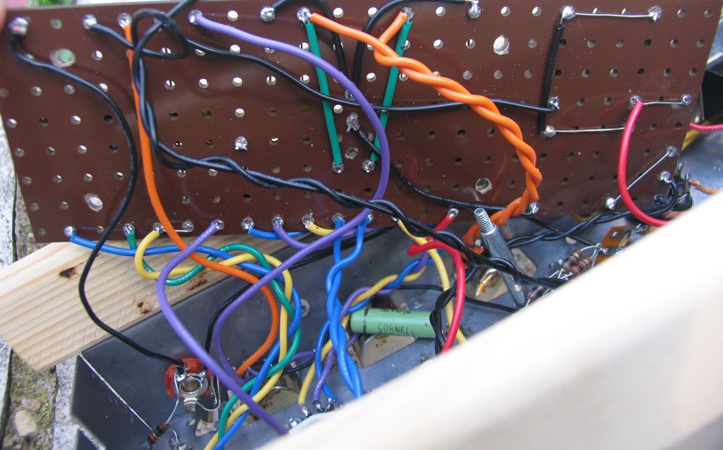
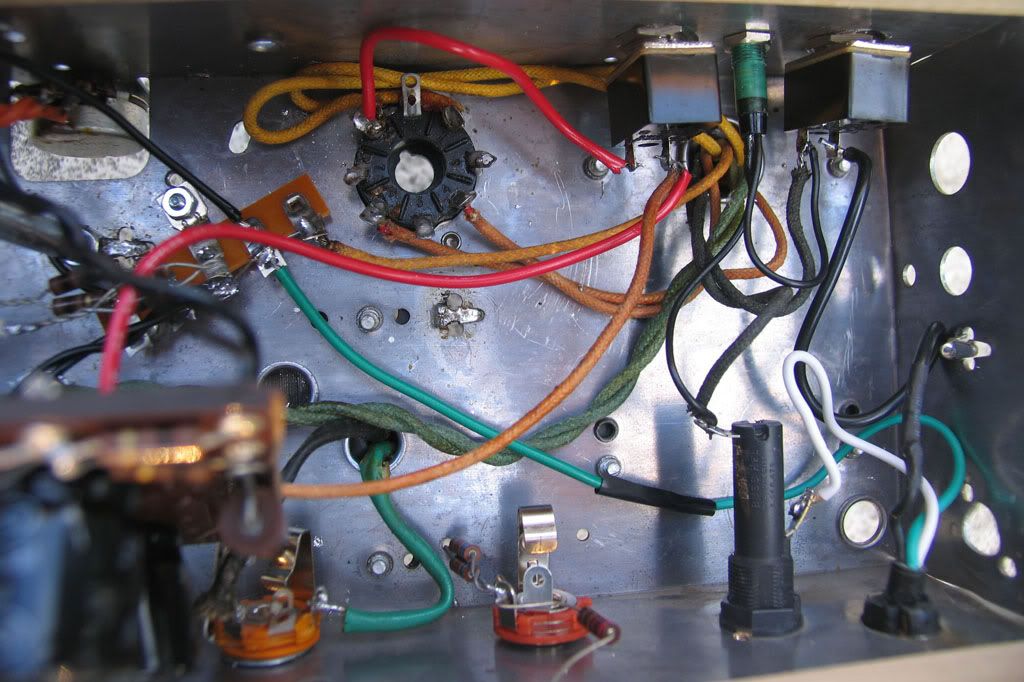
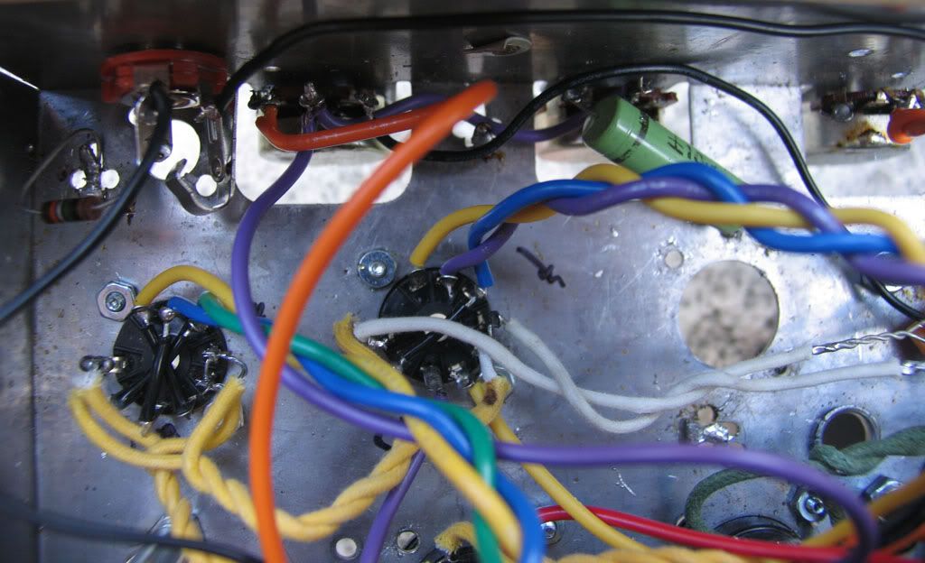
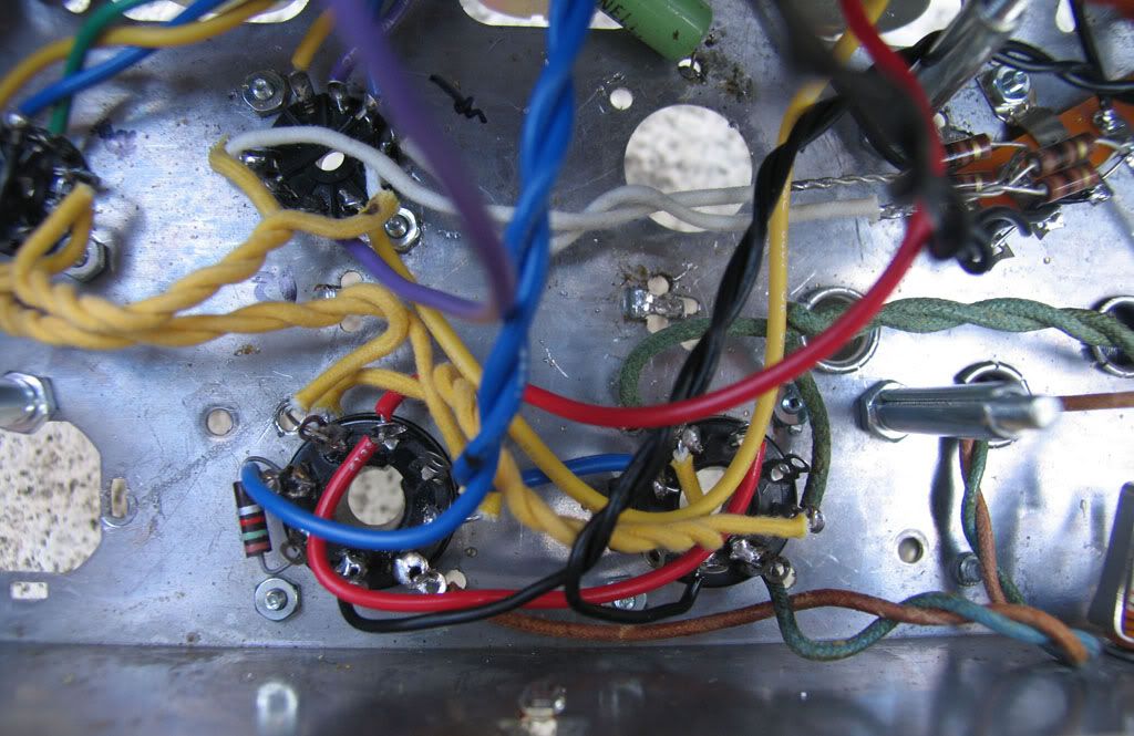
            I did have a minute before it got dark to shot photos of the current (pardon the pun) wiring for reference.

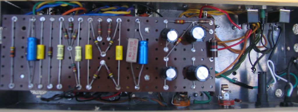
            The board top (sorry for the out of focus)


            Back side of the board. There is some economy in wiring to be had, but I will get to that later.


            The hot side of the chassis.


            Pre amp and pots


            and power tube sockets.

            Comment


            • #21
              figure it out...

              As I traced back through the schematic... I double checked all the grounds and one was missing. While all negative leads from filter caps were connected, the cluster was not grounded. Put in a ground wire and we are good. Still have some buzz and minor issues to resolve (my pots turn backwards)... but all its good otherwise.

              Thanks a million for all the work and help! I really appreciate it.

              .

              Comment


              • #22
                It will take a little more work on the grounds to get the buzz out of the amp. The cluster of ground connections at the filter caps allows the buzz to get into the preamp where it gets amplified. Disconnect the grounds for the two 22uF caps and run wires to ground them at the input jacks.
                WARNING! Musical Instrument amplifiers contain lethal voltages and can retain them even when unplugged. Refer service to qualified personnel.
                REMEMBER: Everybody knows that smokin' ain't allowed in school !

                Comment


                • #23
                  Originally posted by loudthud View Post
                  It will take a little more work on the grounds to get the buzz out of the amp. The cluster of ground connections at the filter caps allows the buzz to get into the preamp where it gets amplified. Disconnect the grounds for the two 22uF caps and run wires to ground them at the input jacks.
                  Thanks - will do! I also have not shielded the signal wire from the input jack to the board. When I do shield that, the shield gets grounded right?

                  Comment


                  • #24
                    Most of the time the shield is only grounded at one end. In this case, without a clear map of all the grounds, it might be lower noise to ground one end to the input jack and the other to the ground side of the 1.5K cathode resistor of the first tube.

                    Since you have that terminal strip (visible in the "Hot side of the chassis" photo) where the HV center tap is grounded, you have started down the path of "Fender Style" grounding. For this style to work, the preamp and phase inverter (V1 and V2) grounds need to go to a separate point on the chassis. These two points can't be connected together on the board. I know this sounds a little confusing, because it is.

                    Edit: I have created a schematic that gives more detail on the grounds. Each black dot is more or less an eyelet or connection at a jack or terminal strip. The blue "wire" is the quiet ground. You had a wire connecting the quiet ground to point X, remove it.
                    Attached Files
                    Last edited by loudthud; 10-06-2009, 07:35 PM. Reason: Added Diagram of grounds
                    WARNING! Musical Instrument amplifiers contain lethal voltages and can retain them even when unplugged. Refer service to qualified personnel.
                    REMEMBER: Everybody knows that smokin' ain't allowed in school !

                    Comment


                    • #25
                      Cool... I will give that a shot. Thanks very much for putting that together. Been doing some reading on grounding theory... your name comes up more than a few times in the search btw. The ground at X was a pseudo center tap arrangement suggested by a buddy.

                      One more questions... would like to tweak it a bit and try to get some more brights? My schematic currently does not have the 180pF Cap and the cap out in front of the volume is a .022 not a .0022. Will that do it?
                      Last edited by smolder; 10-07-2009, 03:32 AM.

                      Comment


                      • #26
                        The 180pF will add highs but only when the volume control is less than max. You can use different values, anything from 100pF to 470pF. Some people install a switch to select different caps. A SPDT center off switch allows you to select one of two different caps or none at all.

                        Changing the .022uF to .0022uF will give a roll-off to the bass. Something inbetween may be your preference depending on the speaker you are using. Experiment and have fun. Again, you could install a switch to select different caps. There was a thread recently about how to eliminate pops when changing the switch.
                        WARNING! Musical Instrument amplifiers contain lethal voltages and can retain them even when unplugged. Refer service to qualified personnel.
                        REMEMBER: Everybody knows that smokin' ain't allowed in school !

                        Comment


                        • #27
                          good job loudthud. im planning to do a spitfire w/6v6's, does anything need to be changed besides rewiring the power tube sockets?

                          Comment


                          • #28
                            Originally posted by scole View Post
                            good job loudthud. im planning to do a spitfire w/6v6's, does anything need to be changed besides rewiring the power tube sockets?
                            I found a reference (I did a search) on the 18watt sight for converting a schematic to 6V6's... and used those cap/resistor values as a guide. Unfortunately I did not bookmark the page.

                            Comment


                            • #29
                              Originally posted by scole View Post
                              good job loudthud. im planning to do a spitfire w/6v6's, does anything need to be changed besides rewiring the power tube sockets?
                              To properly bias 6V6s, the cathode resistor for the output tubes will need to be something between 250 and 330 ohms (as done here) and the screen resistors could use an increase from 100 ohms to 470 ohms. IMHO the Spitfire's screen resistors are too small and the amp will stress EL84s. This will depend somewhat on the primary impedance of the output transformer and B+ voltage.
                              WARNING! Musical Instrument amplifiers contain lethal voltages and can retain them even when unplugged. Refer service to qualified personnel.
                              REMEMBER: Everybody knows that smokin' ain't allowed in school !

                              Comment

                              Working...
                              X