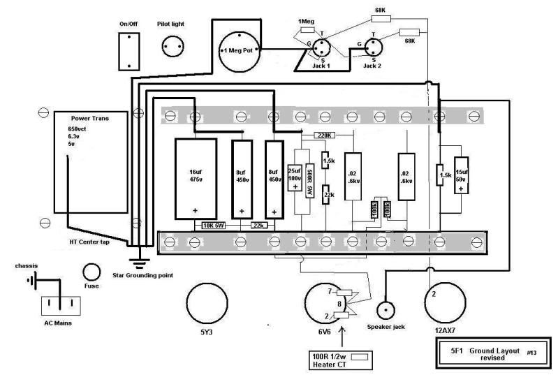
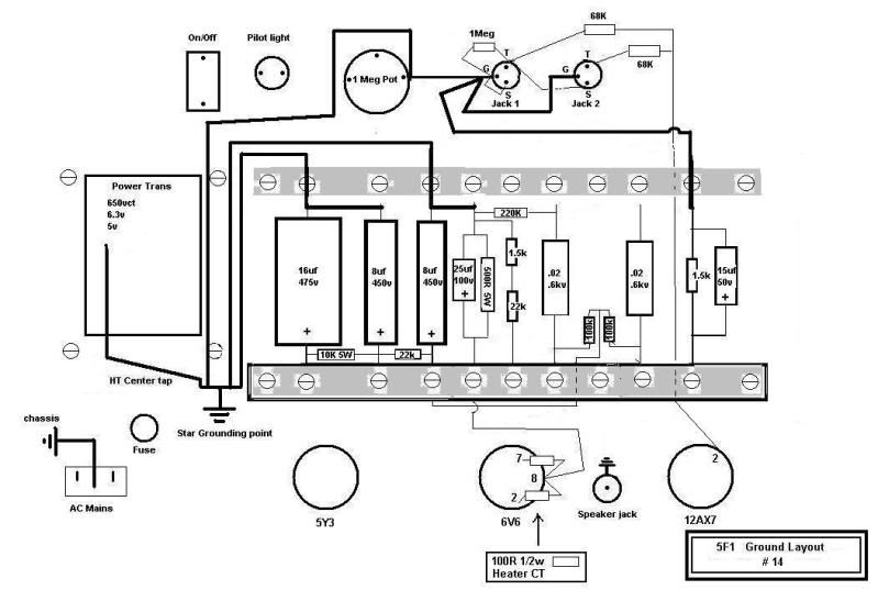
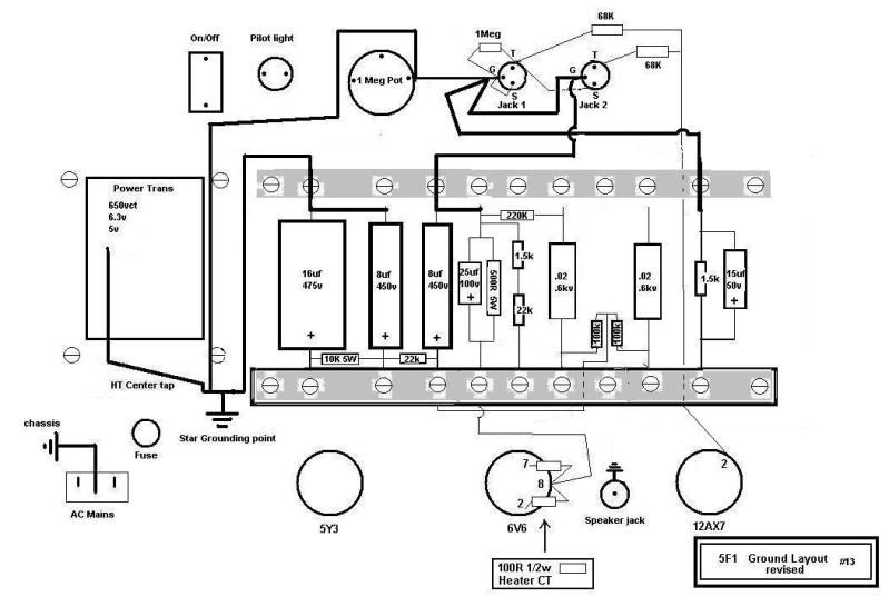
Hi electrochronic. I meant that each ground return component should have its own separate respective wire to the common grounding point in question. So for the grounding point at the input jack , there should be one wire coming from the vol pot ground, one wire coming from the cathode resistor ground of V1a, one wire coming from the cathode resistor ground of v1b, one wire coming from the grid resistor ground of v1a, 1 wire coming from the pre-amp filter cap ground.
Similarly for the 'high-current' ground, there should be one wire coming from the 6V6G grid load resistor ground, 1 wire from the cathode resistor ground, one wire from the screen node filter cap ground, 1 wire from the reservoir filter cap ground, 1 wire coming from the High-Tension CT, and, if you're not going to elevate the heaters at the 6V6G cathode, then also one wire coming from the heater CT (or the artificial ground referencing 100R resistors).
The ways you have it drawn in those previous 5 examples, each of the ground reference points appears to share a ground return path with other ground reference points. That will increase the possibility of differences in ground potential inducing hum into the signal path.
Well that way works for me. Another thing I use is reasonably thick multi-stranded copper wire for each ground wire. That minimises the resistivity of each connecting wire.


Comment