Ad Widget

Collapse

Announcement

Collapse
No announcement yet.

5F1 - hum and speaker crackle

Collapse
X
 
  • Filter
  • Time
  • Show
Clear All
new posts

  • #46
    Hi electrochronic. I meant that each ground return component should have its own separate respective wire to the common grounding point in question. So for the grounding point at the input jack , there should be one wire coming from the vol pot ground, one wire coming from the cathode resistor ground of V1a, one wire coming from the cathode resistor ground of v1b, one wire coming from the grid resistor ground of v1a, 1 wire coming from the pre-amp filter cap ground.

    Similarly for the 'high-current' ground, there should be one wire coming from the 6V6G grid load resistor ground, 1 wire from the cathode resistor ground, one wire from the screen node filter cap ground, 1 wire from the reservoir filter cap ground, 1 wire coming from the High-Tension CT, and, if you're not going to elevate the heaters at the 6V6G cathode, then also one wire coming from the heater CT (or the artificial ground referencing 100R resistors).

    The ways you have it drawn in those previous 5 examples, each of the ground reference points appears to share a ground return path with other ground reference points. That will increase the possibility of differences in ground potential inducing hum into the signal path.

    Well that way works for me. Another thing I use is reasonably thick multi-stranded copper wire for each ground wire. That minimises the resistivity of each connecting wire.
    Building a better world (one tube amp at a time)

    "I have never had to invoke a formula to fight oscillation in a guitar amp."- Enzo

    Comment


    • #47
      Bullshit! Your amp will work fine, without oscillations, with a PP transformer wired for SE operation (use the whole of the primary winding & cap off the centre tap, double check that your impedances are matched...though double/half the rated load will not cause the symptoms that you have). Yes, it is best to go with a SE OT, but running a PP OT will not prevent the amp from functioning. Why not use a New Sensor/Hyboer Champ OT?

      Comment


      • #48
        Tubeswell,

        Well, I'm really dragging this out, aye - basic grounds layout 101. I think this is a good lesson for all who are dropping in to read and learn.

        tell me if I'm getting closer.


        MWJB

        As soon as I get a " good to go " layout approval, I'll rebuild this amp with
        this current transformer and see If the oscillation problem disappears, if not
        then I'll try a single ended trasnformer. I ran my current PP transformer with the center tap on the primary tied off - no connection. Since this is a universal transformer, it has selectable primary impedances , but the secondaries are not selectable. you just look at the setup chart under your speakers impedance and select
        the two taps that give the desired primary impedance. The secondary impedances 4,8,16 are sensed.

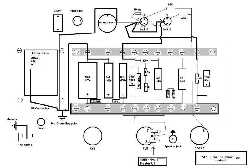
        Here's the new layout - take 13

        Last edited by electrochronic; 12-14-2009, 10:56 AM.

        Comment


        • #49
          You just have 1 grounding point?

          Your speaker jack appears to be grounded to V1 cathode? Doesn't your speaker jack ground though the socket connection to the chassis? It should.

          Preamp grounds (V1 cathodes & preamp filter cap) should ground at input jack ground (via jack's physical connection to chassis)...I'm getting deja vue here...

          Your #2 pin for 12AX7 seems to be around the 11 o'clock position? Meaning pin 7 should be around 5 o'clock? Rotate the 12AX7 socket by 180 degrees OR wire pin 6, 7, 8 as your input triode and 1, 2, 3 as your tone recovery triode. You currently have the signal crossing back over itself, which is never a good idea. Components should line up as much as possible with the tube socket pin that they feed.

          Comment


          • #50
            You just have 1 grounding point?
            Yes, One ground point. every connection has one path to ground.
            One path each to one ground. Is this wrong ?

            Your speaker jack appears to be grounded to V1 cathode? Doesn't your speaker jack ground though the socket connection to the chassis? It should.
            yes, the output jack is normally grounded to chassis , I will keep it this way. I have been told to isolate it and
            tie it to preamp ground for reduced noise.

            12ax7 socket now orientated just as I have it in the chassis, earlier placement
            not accurate. Also, when I run each wire to the tube socket none of the wires cross
            over each other. They are neatly routed to each socket pin and back to components, term strips etc.

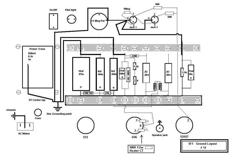
            layout take 14

            Last edited by electrochronic; 12-14-2009, 11:52 AM.

            Comment


            • #51
              On take 15 I'd like to see the preamp filter cap (8uf connected to the RH end of the 22K power supply resistor) grounded at the most RH input jack (preamp ground).

              Too some degree, I feel that you are making life harder for yourself by sticking to the Fender style layout. Your layout is not to scale compared to the photos you posted either. Many of your components could be wired point to point, saving unnecessary wire length, reducing risk of oscillations.

              Comment


              • #52
                Too some degree, I feel that you are making life harder for yourself by sticking to the Fender style layout. Your layout is not to scale compared to the photos you posted either. Many of your components could be wired point to point, saving unnecessary wire length, reducing risk of oscillations.

                Yes, not exact to scale but not far off either. Most of the wired connections are really short.

                My goal at this point is to rid the oscillation and take the steps necessary to clean up the grounds. At this point , I'm not really convinced my ground layout was wired properly as you can see I am still making revisions in the layout. When I arrive at a layout that everyone seems to agree upon then I will build it and see if the oscillation disappears or re-appears. I'm also planning to try a different OT made specifically for single ended amps like this one. There has to be a solution to this oscillation issue. I won't surrender until it I get to the bottom of it.

                Another note the input jacks are grounded to the chassis ( not isolated ) just like the output jack, and the inputs are switched. Now , do I still need to wire them like in the schematic below or will I get ground loops ?


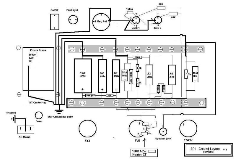
                Layout Take 15
                Last edited by electrochronic; 12-14-2009, 01:47 PM.

                Comment


                • #53
                  It's normal for the buss wire to continue from the pot(s) to the farthest right hand jack socket. Have your V1 cathode resistors ground to the same place you have the preamp filter cap grounded.

                  Otherwise, yes, ground as "take 15". It is normal for guitar amps using metal switchcraft style jacks (as opposed to plastic Cliff jacks) to have the jacks ground at their connection to the chassis.

                  The ground wire going from the pot to PT bolt ground, may not be necessary - try with & without this wire, go with whatever gives the least noise.

                  Comment


                  • #54
                    What MWJB just said.

                    (Each one of the pre-amp ground return points (incl pre-amp filter), each by its own separate wire, goes to one (and only one) of the input socket grounds. The other input socket doesn't need to be grounded if its bolted tightly enough to the chassis.

                    Each one of the other ground return points, each by its own separate wire, goes to the 'other' ground return point.

                    Try it without the link between the vol pot and the other ground return point. That might make for an unwanted ground loop.

                    Sorry if I didn't make myself clear all the other times.)

                    Try it that way and see it it makes any improvement
                    Building a better world (one tube amp at a time)

                    "I have never had to invoke a formula to fight oscillation in a guitar amp."- Enzo

                    Comment


                    • #55
                      Just spoke with Hammond technical support today and they confirmed that I was sold the wrong output transformer. They said my Hammond 125C universal OT does not have a gapped core to prevent unwanted saturation caused by excess dc that can cause nasty oscillations like the one I am experiencing. They are aware of the problem associated with my amp. They said that I must use the 125 "SE" version universal or any other OT intended for a single ended output stage.

                      So this should take care of my oscillation problem , ordered a transformer today. I decided to buy a Weber 6-15w 4/8 ohm secondary $30. Hayboer wanted $70, yikes. Edcor Xse $20 , but almost two month backlog. This will allow me to run a champ using a 6L6 output tube. I also have a extra power transformer on standby for the extra current needed for a 6L6 and 5U4 rectifier tube for a later build. The 8 ohm tap will allow me flexibility too use 10" speaker too. many options.

                      When you buy your kit to make a champ make sure you never trust the guy behind the counter to sell you the correct parts. They will most likley randomly sell you something you might not need. Choose for yourself.

                      In my case I can take my Hammond 125C and build a PP 6BQ5 , 6V6, or 6AQ5w tube amp. So this transformer will be handy for a future build.


                      Nevertheless, Still want to get my grounding layout cleaned up , so thanks for sticking with my lengthy
                      thread.
                      Last edited by electrochronic; 12-15-2009, 02:51 AM.

                      Comment


                      • #56
                        I rebuilt my Champ 4 times. Each time I would fix one issue and another would come up I did not think about. I got it right on the 4th version. Just goes with the territory.

                        Comment


                        • #57
                          Utter horse doo doo!!!

                          They are talking out of their backsides. Just changing the OT (without changing anything else) is most unlikely to cure your oscillations! Take a Super Reverb, pull out one power tube...what happens? You get a drop in headroom, but you don't get oscillations.

                          If you have a 125P1B PT that will cope happily with a 6L6, upgrade your cathode resistor to 10W, use a 100v rated bypass cap. You'll probably need to use a GZ34/SS rectifier to stop power dropping with a 6L6.

                          Comment


                          • #58
                            Solve this issue? I have something that seems very similar...

                            Comment


                            • #59
                              Of the suggested remedies posted, what have you tried?

                              Post pics of the build under a new thread.

                              Comment


                              • #60
                                Just thought I 'd drop by to let you folks know that after receiving the correct single ended transformer the Champ amp is now working as it should.

                                Good thing I did this otherwise, I would have been troubleshooting down the wrong road. Hopefully, next time this problem occurs for someone else they can use my experience to get it right.

                                The grounding issues and layout had knothing to do with the transformer oscillation/overloading
                                problem , two totally separate issues in this case. The amp work sgreat and is quiet as can be.

                                this is not to say that some of the grounding techniques discussed here were faulty, they were'nt. In Fact,
                                the single biggest improvement is to use a 2(100) ohm resistor if your PT trasnformer does not have a center tap
                                like mine. Also , changing the ground potential on this suedo center tap and placing it at a elevated ground
                                potential of 1.5Vdc at the positive side of the 25/25v cap made the greatest improvement in removing hum
                                from this build.


                                MWJB , I can't figure out why you insist that the OT was not the problem. However in this case , it was.

                                There is a huge difference in the way a SE transformer is made compared to the PP transformer. There is a gap
                                that is created in one and not the other , this sets them apart. It has a dramatic effect. You should try it on the
                                bench. If a PP transformer can be used as a SE transformer then I have not seen a circuit in which it shows a optimized layout that will allow it to work. If you know of one I would be happy to bench test it.
                                Last edited by electrochronic; 01-18-2010, 05:31 PM.

                                Comment

                                Working...
                                X