Ad Widget

Collapse

Announcement

Collapse
No announcement yet.

Carlsbro 60 watt twin channel

Collapse
X
 
  • Filter
  • Time
  • Show
Clear All
new posts

  • Carlsbro 60 watt twin channel

    i've had great success with my last post i think if i stick around long enough, i'm bound to learn something.
    since i dont really have that much advice to offer here i'll ask for some more instead

    i was gigging with this amp for about a year it started to act very strangely so i stopped using it in favour of a fender transistor combo.
    its been next to my wardrobe since

    i have found
    http://music-electronics-forum.com/t12724/
    and
    http://music-electronics-forum.com/t2082/

    both of which are carlsbros with tube related issues, but not exactly the same.

    the amp was fine and besides a few quirks which at the time i just didnt understand, sounded awesome.

    i put it to the side after a weird sound at practise and only one tube was lit. (not a pop, squeal or crackle... just sounded odd while playing)
    i discovered a physically cracked tube. (el34)

    i changed it out for another and turned the amp on. it was definitely working but the tube i had put in started to glow seriously hot straight away. i turned it off and swapped the tubes around and the same socket made the tube glow again, i didnt give it much time before turning it off just in case. i guess whatever causes this was what made the original one crack?.

    i'm not sure how long i ran it with one output tube but i'm sure thats not good for it.
    if i am to do any of the tests suggested before, there are a couple of things i really would like cleared up first. just to make sure i dont do any damage to the amp.

    1. in the posts above there are some tools for checking tubes and bias although i was under the impression i could do this with a multimeter?
    do i need these?

    2. secondly, i want to make sure i dont hurt the OT... so
    if i turn the amp on i ALWAYS have a load connected, is this needed if in standby?

    3. how safe is it to turn on the amp with no tubes in?

    4. how likely is it that my load (speakers) will suddenly put out something at full volume while testing? i guess this one isnt really as important as the others

    greatly appreciate any help or advice

  • #2
    Firstly it makes life a lot easier if your output tubes are a reasonably well matched pair. Most of the time you may get away with a random selection, but you may have tubes that are way different, ie the same bias voltage at the grid causes 1 tube to run at 5mA, the other at 50mA.
    If you want a big warm bottom end to your tone, a reasonable match (<10mA discrepency) is necessary.
    1. to check bias you just need a reasonable multimeter with a dc milliamp range (good accuracy / resolution at around 30mA), and fit a 1ohm 1% accuracy resistor (>=0.5watt)between each power tube cathode and it's ground return. When powered up, the mV across the resistor = the mA through the tube. Ideally a test load resistor, signal generator and preferably an oscilloscope also. Read the biasing link on the aiken site in link below to get your head around the concepts.
    2. generally, no load is needed for the OT when in standby. Some selmars leave the supply to the OT on when in standby and just switch the screens and preamp off, so if your's is like that then when messing around with it, it might be best to keep a load connected.
    3. generally there's no problem powering an amp up with no tubes in. However, best to check all the power supply bigh voltage caps to ensure that the voltage across them doesn't rise above their max rated voltage.
    4. it depends how you're testing it. Plus a problem amp may generate all sorts of nasty noises, so best to use a test load resistor and tap a bit of the amp output off to a speaker via a 1k resistor so you can hear what's going on.

    For you situation, as an initial check I would take the el34s out, power the amp up and measure what bias voltage is getting to the grid terminal on the tube base.

    From the tone of you post, I'm not sure how experienced you are with working on high voltage equipment, so please read the 'safety advice' links here
    Links to amp building forums and resources
    and ask if you don't fully understand anything. Pete.
    My band:- http://www.youtube.com/user/RedwingBand

    Comment


    • #3
      hi pete.
      thanks for your reply. that clears it up somewhat. i'll remember about the load if i ever need to get into my selmer too.

      you mentioned my experience, and i have to admit i am pretty new to this but i am steadily picking things up.

      i think its important to mention my main priority when i've done anything like this, is being constantly aware of the dangerous high voltages .
      i am very slow and very careful whenever i attempt anything like that, just in case. i have also tried to maintain the habit of keeping my left hand on my plastic meter at all times.

      i do like to ask questions and make sure before guessing.
      i'm definitely in no rush either.

      i appreciate the starting point you've given me and i'd like to check that out straight away.
      on that note just to confirm i'm doing the right thing...

      the test you suggested :
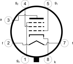
      is this picture looking at the pins from the under side of the tube or looking at the socket from outside the chassis?

      although i guess the numbers may be on there.

      there are 3 grids in the tube, will that be the middle one that i measure?

      i am checking this voltage to ground?
      cheers
      kev.

      Comment


      • #4
        ok, so the numbers are both on the tube and the socket thats simple enough.

        i still cant see about the grid connection from the schematic what the numbers are on the connections its blurry. is there a standard for el34's?

        Comment


        • #5
          Pin 5 is the grid that should have a -V bias voltage on it. Unless your amp is cathode biased. I'm not familiar with that amp.

          And I think your right about the problem with that socket causing the first tube failure because when you swapped tubes the problem followed the socket, not the tube. However, as mentioned, matched tubes are best. But I wouldn't trouble to plug in matched tubes before fixing the problem with that socket. I suspect it's a bad solder joint, broken lead or a badly corroded or broken socket pin because the non failing socket seems to have bias. Check bias voltage as mentioned and look for any burns, breaks, loose wires, etc. associated with pin 5 of the offending socket.

          Chuck
          "Take two placebos, works twice as well." Enzo

          "Now get off my lawn with your silicooties and boom-chucka speakers and computers masquerading as amplifiers" Justin Thomas

          "If you're not interested in opinions and the experience of others, why even start a thread?
          You can't just expect consent." Helmholtz

          Comment


          • #6
            Carlsbro 600 T.C. Amp Schematic
            i believe thats the right one.

            just to make sure.
            am i measuring DC to ground from each el34's pin 5 out.

            right?

            Comment


            • #7
              Yep. Pin 5 to ground. It's hard to read the schematic. Is it -37V?
              ST in Phoenix

              Comment


              • #8
                Yes, the points marked -37V are the ones of concern.
                It's also possible that even though the correct voltage appears there, the female contact in the base socket isn't making reliable connection to the EL34 pin (look for threads regarding 're-tensioning' tube bases). So a thorough examination of the base is needed if the voltage seems ok. Also wiggle the 100k and 10k resistors with something insulated whilst monitoring the voltage. A dodgy connection or component might cause intermittant bias.
                My band:- http://www.youtube.com/user/RedwingBand

                Comment


                • #9
                  ok theres -35 on each

                  Comment


                  • #10
                    Hmmm???

                    What would cause a particular socket to red plate any tube you plug in even with bias voltage present???

                    35V is close enough for now. The problem is likely something else. I wouldn't call your board conductive with those readings. Maybe one half of your OT primary is shorted. Maybe the EL34 socket pins are loose or dirty and either fail intermittently or touch pin 5 to another when a tube is plugged in. It could be that the socket is conductive but only demonstrates with a tube plugged in and drawing current.

                    The fact that the problem is with the socket but that there is bias voltage present makes this tricky. For me at least.

                    Chuck
                    "Take two placebos, works twice as well." Enzo

                    "Now get off my lawn with your silicooties and boom-chucka speakers and computers masquerading as amplifiers" Justin Thomas

                    "If you're not interested in opinions and the experience of others, why even start a thread?
                    You can't just expect consent." Helmholtz

                    Comment


                    • #11
                      A really beneficial mod I've found is to put fuses into the cathode ground return of each power tube. 315mA quick blow for 6L6 and EL34 - you can use quick blow here are there aren't any cap charging surge currents.
                      Fit the 1 ohm resistor between the fuse and ground.
                      Turn the bias voltage to it's max negative setting.
                      After you've made the tests mentioned in my prev post, fit the tubes, power up and monitor the voltage across the 1 ohm resistors.
                      My band:- http://www.youtube.com/user/RedwingBand

                      Comment


                      • #12
                        well i will check again and make sure nothings being shorted when i put the tubes in etc.
                        the mod sounds interesting.
                        does that prevent things like red plating then?
                        i would like to do that but not sure how i would physically go about it...
                        chassis mounted fuse sockets with trailing wires or an insulated inline type? or maybe theres another way?

                        i added some pics thats always good.

                        which is the bias adjuster? i read on the carlsbro forum theres a trim in there which is not bias and i shouldn't touch it.


                        Comment


                        • #13
                          theres definitely nothing else underside on the of the tubes. its all solid and the connections are well away from the others even when i rotate the tubes slightly.
                          also checked the resistors that look like they're dangling under the tubes and they check out fine too.

                          should i do that fuse mod? is that necessary for figuring out whats going on here?

                          Comment


                          • #14
                            The bigger trim pot is the bias adjustment.

                            The fuse mod won't fix anything. It's a preventive circuit to protect the tubes in the event of a circuit failure. I'm not saying it's a bad thing to do, but if you want to use the mod to protect tubes while troubleshooting this problem you may need a lot of fuses (which ARE cheaper than tubes). Still, I'm puzzled that you have a good bias read on both sockets and one of them always red plates the tube that's in it

                            If you can get a voltage read on all power tube socket pins before blowing up a tube that may help.

                            I'm thinking OT but look up inside pin 5 of the offending socket (where the pin goes in) to see if it may be really loose, busted off inside or badly coroded. Having bias on the tube socket won't do any good unless it gets to the tube.

                            Chuck
                            "Take two placebos, works twice as well." Enzo

                            "Now get off my lawn with your silicooties and boom-chucka speakers and computers masquerading as amplifiers" Justin Thomas

                            "If you're not interested in opinions and the experience of others, why even start a thread?
                            You can't just expect consent." Helmholtz

                            Comment


                            • #15
                              Can your meter measure 500V DC? If it can, I'd be curious to know what the voltage is on each of the 3 wires of the output transformer. From your pics, it looks like you need to check between ground & pin 3 on each tube socket (yellow wire on 1 & black on the other) & also check pin 6 on both sockets where the red wire is. I don't have alot of tube amp experience, but it looks to me like those should all be 500V DC.
                              ST in Phoenix

                              Comment

                              Working...
                              X