Ad Widget

Collapse

Announcement

Collapse
No announcement yet.

Ampeg v2 red plate help!

Collapse
X
 
  • Filter
  • Time
  • Show
Clear All
new posts

  • Ampeg v2 red plate help!

    Hi. I have an early 70's ampeg v2. When I got it, it was in pretty rough shape, Other than that it has had a recent cap job. I have since then replaced all of the other cap in the amp, and most of the large resistors. The only mods that I know of are:

    Master Volume
    Adjustable bias
    El34 power section (w/ proper screen resistors)
    12ax7 throughout the preamp minus the reverb

    I'm getting a red plate, and a glowing grid on the inside tube only. It only happens when I am putting a signal through the amp and it is turned all the way up. The bias is set very low as well.

    The bias voltage stays constant, so i don't think that is it.
    It does this with 6l6's as well
    Plate voltage stays fairly constant
    Screen voltage jumps all over the place.
    the redplate follows the socket, not the tube.

    I checked the AC voltage going into the control grids of the power tubes. Sure enough, the problem tube is getting at least 20 volts more with the same signal going through. I checked the plates on the PI. same thing.

    I've checked every resistor value, pulled out one lead, checked again. The caps are brand new. stock values all around. I put a 12au7, which is what the design calls for. same thing.

    The PI should put an identical signal into each side of the power tubes. right?

    this is my power amp: http://www.schematicheaven.com/ampegamps/v2powamp.pdf

    I am at a loss. Any help will be appreciated.


    garrett

  • #2
    Ampeg V2 replate

    Can you try a test of the PI circuit without the output tubes in.
    I would look at pin 5 of the OP tubes
    Can you state the AC voltage that is at Pin 5 at full power.
    Can you look at the PI output with a scope?
    That may tell us something.
    We are not talking a bad socket are we?

    Comment


    • #3
      I tested with the output tubes out already. Mostly to save my ears, and the runaway tube. However, I only remember testing the AC on pin 5 of the output tubes. should I test the plates of the PI with the output tubes out? Still a crazy imbalance on pin 5 with the tubes removed.

      I will get some exact numbers as soon as I can get back to the amp. I just remember the numbers being way off from each other. I remember getting as much as 80 volts on the hot tube.

      An oscilloscope is going to be my next purchase. I don't have access to one at the moment.

      I tested the sockets for continuity using a bias checker and testing through it to the other side where the wires go. checked the PI socket too.

      Comment


      • #4
        PI check

        Yeah, check both sides of the Pin 5, PI connection. Should be a capacitor in the middle there.
        You cannot check too much of anything when you are tracking down a problem.
        Divide to conquer.
        Narrow it down to the smallest area of the circuit.
        Figure it out & nail it.
        Happy hunting
        John G

        Comment


        • #5
          Originally posted by Jazz P Bass View Post
          Yeah, check both sides of the Pin 5, PI connection. Should be a capacitor in the middle there.
          you mean a snubber? (i think) I tried doing that, it didn't help.

          Can a PI imbalance go further back than the phase inverter? or is this definitely in the power amp somewhere?

          Comment


          • #6
            Ampeg red plate

            O/k. didn't help what?
            Your looking for something wrong with the circuit.
            The capacitors are blocking caps. The PI plates are at a high potential.
            Caps , till they charge, do not pass DC voltage.
            The reason that I asked you to check is if a cap is bad, it MAY be passing DC.
            That raises your output tube bias grid.
            That may be your Red plate issue.
            You have to check.
            Measure each PI plate voltage.
            Then measure each output tube grid voltage.
            Tell us what you got.
            Last edited by Jazz P Bass; 11-05-2009, 02:02 PM.

            Comment


            • #7
              I will get the data for you tomorrow.

              here is the exact problem I am having:

              Output transformer roasted? - AMPAGE Archive

              Comment


              • #8
                Ampeg red plate

                That sure was an extensive post.
                Don't you love when the post just ends.
                Was it eventually repaired.
                I noticed Steve Connor chimed in.
                He may have a point to consider.
                Heat.

                Comment


                • #9
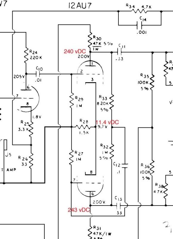
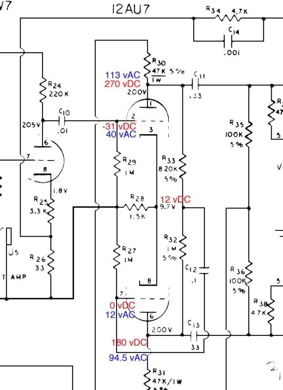
                  Ok, So I feel like I've Puled every resistor in the amp and traced every connection. I can't find a problem, so I gathered some data with and without a signal applied. I used a frequency generator program on my ipod touch. I forget the frequency, but it was audible. The voltages are a little high because I did it without the power tubes in. The idle voltages were pretty close to spec with the power tubes in. It is a different story when you apply signal. Hopefully somebody can help. I will have an oscilloscope in less than a week, so I will poke around with that as soon as it comes.

                  At idle, no signal


                  Full volume

                  Comment


                  • #10
                    Also, one thing that I thought was weird. I measured the resistance from pin 2 to pin 2 to pin 3 and got 1M. shouldn't I get 2.5M ohm since the 2 resistors are in series? Same thing with pin 7 and 8. The resistors measure correctly when I test them by themselves.

                    Comment

                    Working...
                    X