Ad Widget

Collapse

Announcement

Collapse
No announcement yet.

Marshall JCM800 2203 Blowing Mains Fuse

Collapse
X
 
  • Filter
  • Time
  • Show
Clear All
new posts

  • Marshall JCM800 2203 Blowing Mains Fuse

    Hello! I have some background in electronics and am taking proper precautions to work inside an amp with this much wattage but need some help tracking down the problem I'm having. My JCM800 2203 has started blowing the T2A mains fuse when running at 8ohms into an 8ohm Carvin BR12 speaker. It happens after 15-20 minutes of playing at loud volumes.

    I've checked the 6550 tubes with my tube tester - all read strong and didn't come up with any shorts. I didn't see any red-plating either while watching them. Also tapped them with a chopstick and didn't hear any "chunk" or see any weird arcing inside the glass. I checked the grid screen resistors and all read just under 1k Ohms. None read open.

    The amp IS noisy -- kind of a static-y background idle hum. The bass is also rather weak. I borrowed a buddy's Anatek ESR meter and checked the five 50uf/50uf 500v filter caps.

    1st Can (furthest from group of four)
    Red .39
    Yellow .43

    The rest of these capacitors appear to be wired in series.

    2nd Can
    Red .22
    Yellow .21

    3rd Can
    Red .21
    Yellow .23

    4th Can
    Red .30
    Yellow .31

    5th Can
    Red .19
    Yellow .20

    The filter caps don't have any signs of leaking or pimpling but they are pushing 30 years if not more as they appear to be original to the amp.

    I would appreciate helpful suggestions or ideas. Thank you!

  • #2
    JCM800 2204 6550 Output

    Is this the JCM800 2204 that is meant for 6550's?

    In that case, I show a 3A Time Delay fuse is in order.

    There are a number of changes to go from EL34 to 6550.
    Most important is the bias voltage on the output pins.
    The schematic shows a raw -57Vdc for 6550's.
    Attached Files

    Comment


    • #3
      Hi! It's a model 2203. The rear panel on the chassis indicates the mains calls for a T2A fuse. The grid screen resistors are 1k ohm units which is in line with 6550's and EL34's. Bias caps are 10 uf 100v. Possible that this amp was modded before I happened upon it?

      Comment


      • #4
        The grid leak resistors are 150k ohm wirewound resistors and r26 is a metal film 42.3k resistor. From what I gather the English JCM800's had EL34's in them and the North American models had 6550's. Since the parts in here are not carbon comps like the rest I guess it was modded for EL34's and then returned to stock with 6550's.

        Comment


        • #5
          Not sure which schematic you are getting component names from (R26), or is that labelled on the board?
          http://www.drtube.com/schematics/marshall/jcm800pw.gif
          I take it that R26 is the one connected to the bias trimmer? Is the one feeding the bias rectifier 15K or 27K?

          Regardless, you have an amp that was working right and is now blowing the fuse. You have tested the tubes with a tester but that will not show all faults.
          The first step I would suggest is trying other known good power tubes.
          Originally posted by Enzo
          I have a sign in my shop that says, "Never think up reasons not to check something."


          Comment


          • #6
            Originally posted by g-one View Post
            Not sure which schematic you are getting component names from (R26), or is that labelled on the board?
            http://www.drtube.com/schematics/marshall/jcm800pw.gif
            I take it that R26 is the one connected to the bias trimmer? Is the one feeding the bias rectifier 15K or 27K?

            Regardless, you have an amp that was working right and is now blowing the fuse. You have tested the tubes with a tester but that will not show all faults.
            The first step I would suggest is trying other known good power tubes.
            Correct, it is labeled on the board as R26.

            There's a 15k resistor between one of the bias caps and the group of diodes.

            I replaced the Sovtek 6550's that were in there with some Winged C 6550's. I haven't had a chance to test it out.

            I'll try to get a picture up of the board. In the meantime, I'm pretty confident that this amp was originally shipped with EL34's and has been modded to accept 6550's. How can I go about measuring the bias with a digital multimeter? I lack octal plugs.

            Mind you, I will not proceed with that 'til I'm fully assured I'm doing it right. I am acutely aware the voltages in this amp are lethal.

            Thanks again!

            Comment


            • #7
              Originally posted by bigchief View Post
              There's a 15k resistor between one of the bias caps and the group of diodes.
              There should be another between the bias diode and the bias winding of the power transformer, 15K for 6550, 27K for EL34. Not critical, but might as well make sure it's right.

              Originally posted by bigchief View Post
              How can I go about measuring the bias with a digital multimeter? I lack octal plugs.
              There is a method I sometimes use that I call the "death wish" method (AKA shunt method), but it is VERY dangerous. The best way is to break the connection between pin 8 of each power tube and ground, then install 1 ohm resistors between pin 8 and ground for each power tube. Then you just measure the voltage across the resistor, and you will know the cathode current (1mV across 1ohm = 1mA).
              Originally posted by Enzo
              I have a sign in my shop that says, "Never think up reasons not to check something."


              Comment


              • #8
                Apologies for the disappearance! Had life get in the way for a week or so.

                Originally posted by g-one View Post
                There should be another between the bias diode and the bias winding of the power transformer, 15K for 6550, 27K for EL34. Not critical, but might as well make sure it's right.


                There is a method I sometimes use that I call the "death wish" method (AKA shunt method), but it is VERY dangerous. The best way is to break the connection between pin 8 of each power tube and ground, then install 1 ohm resistors between pin 8 and ground for each power tube. Then you just measure the voltage across the resistor, and you will know the cathode current (1mV across 1ohm = 1mA).
                That does sound dangerous!!! My background is mostly hobbyist-type stuff with low voltages. Maybe I should invest in some octal plugs and a unit to measure bias safely...

                The resistor in R30 coming off the power transformer is 27K. Should I assume that whoever modded this to use 6550's previous half-assed the job and it should be changed to 15k?

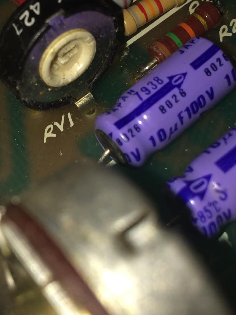
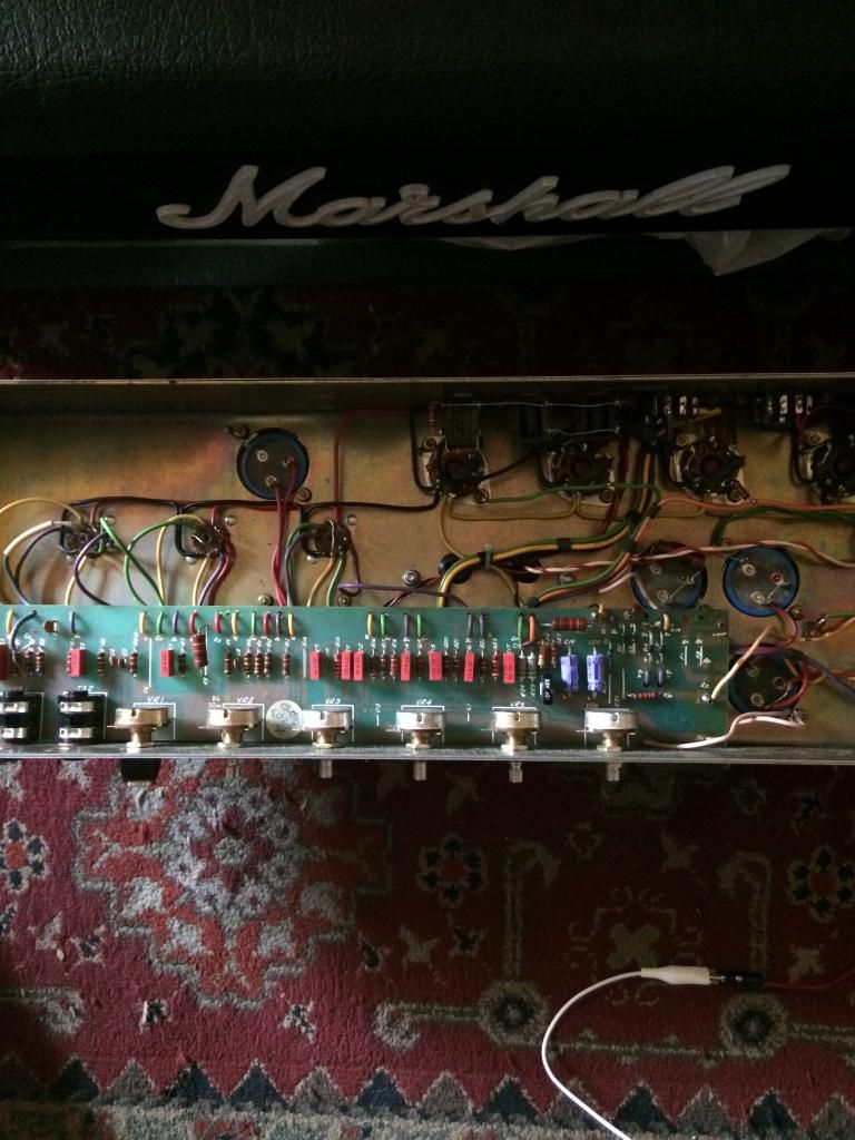
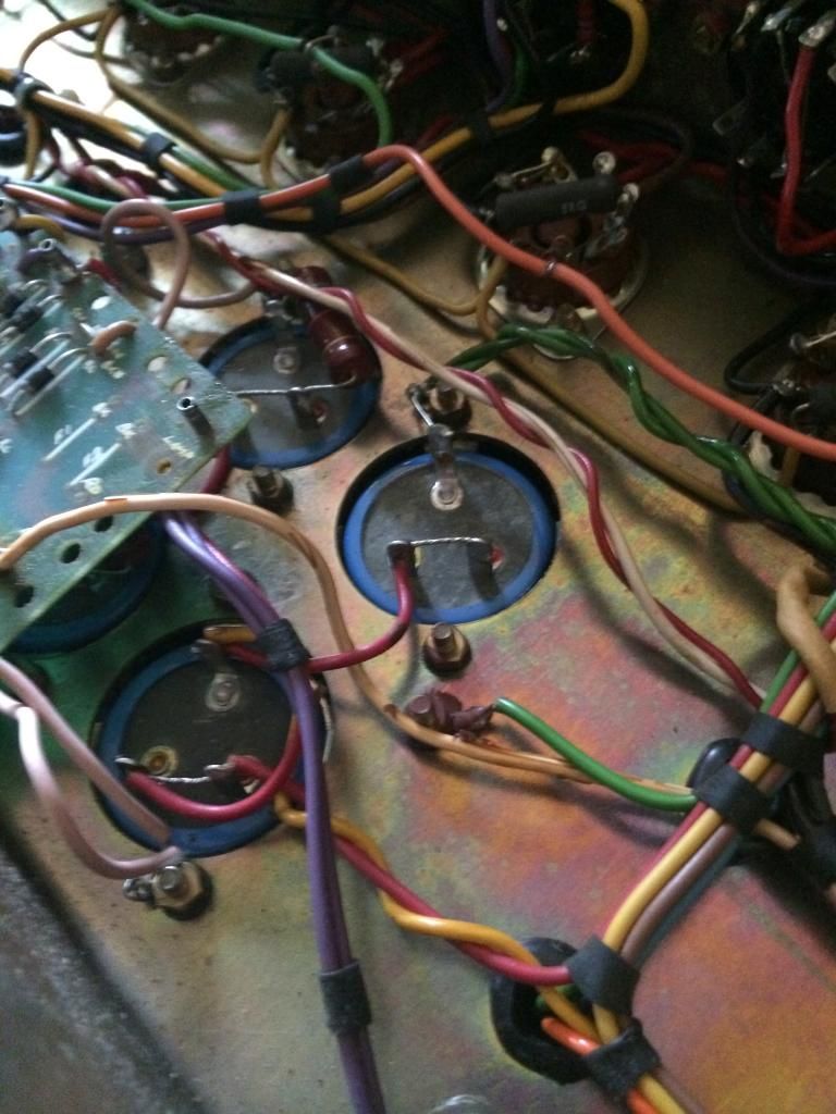
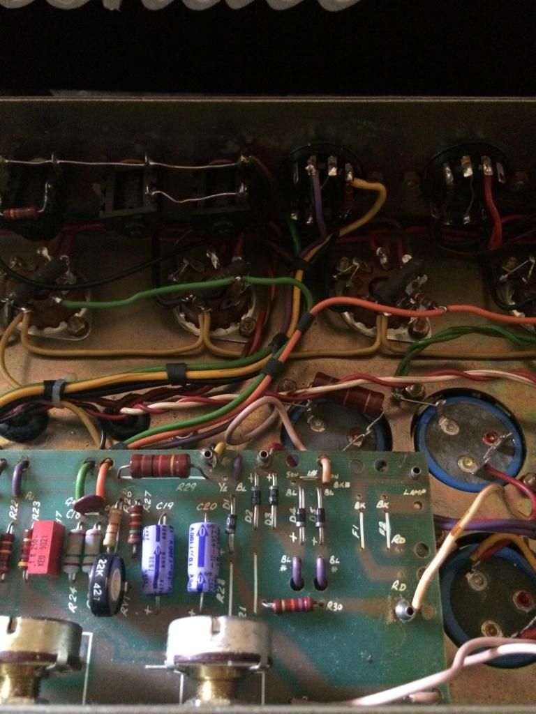
                I have some pictures of the inside of the amp. You can see that some of the resistors have been changed on the left side of, and above the bias trim-pot. What I found to be interesting is that upon closer inspection one of the bias caps appears to be bulging on one end and has a little bit of what looks like electrolytic fluid. It may be bad? The Anatek Blue ESR indicates both are healthy with readings of 1.2 on the meter read-out so idk. Is it possible I have a fluctuating bias that's causing the amp to blow the mains fuse??


                Thank you.

                Comment


                • #9
                  I can't see from the pic, but if a bias cap looks at all suspicious, replace it. Actually, replace them both. Bias circuit failure can be catastrophic, so best to err on the safe side.
                  I would guess who ever made the change over to 6550's missed that resistor, if you are going to stay with them you may want to chage it. However, they may have wanted to be able to run either 6550 or EL34, and it's possible they couldn't get enough range out of the bias adjustment pot with the 15K installed (EL34's use much lower bias voltage).
                  The adding of the 1 ohm cathode resistors I mentioned for bias checking is not the dangerous shunt method. It is the preferred method and does the same as the octal plugs do, but stays with the amp as a permanent install.
                  Originally posted by Enzo
                  I have a sign in my shop that says, "Never think up reasons not to check something."


                  Comment


                  • #10
                    Well I tested the old bias caps vs. some new non-polarized ones and the new ones had an even lower ESR reading. Something like .57 vs. 1.2

                    I've been playing the amp for a bit. Not near full-blast where the problem seems to occur but it seems to be ok. I've noticed the power tubes are extremely hot to the touch, however.

                    I ordered a bias tester from eBay before your post showed up earlier today, g-one. It should arrive in a couple days. Initially I was unclear on the method you outlined but I think that the fact the shunt resistor is mounted internally inside the bias probe on pin 8 and doesn't require me to keep my left handed pocketed while standing over a live amp brings me some peace of mind.

                    Comment


                    • #11
                      Took bias measurements

                      1st Tube 34.3ma
                      2nd Tube - 29.9ma
                      3rd Tube - 37.4ma
                      4th Tube - 34.9ma

                      Seems like there's a bias mismatch with the inner two tubes. Also, that seems rather cold for 6550's does it not?

                      I took plate voltage measurements too and they're 456v. The Sovtek 6550WE's in the amp right now do 42-44 watts max. Ideally I'd want them around 25-30 watts so I did the math.

                      27.5 watts/456v = .0603 or 60.3mv. So right now my tubes are running about half as hot as I'd want them to be.

                      How do I go about testing to see why the 3rd tube is running so much hotter than it's companion tube in the middle? And would it be safe to turn the bias trimpot up and look for red-plating or would that be a bad idea?

                      Comment


                      • #12
                        Originally posted by bigchief View Post
                        1st Tube 34.3ma
                        2nd Tube - 29.9ma
                        3rd Tube - 37.4ma
                        4th Tube - 34.9ma
                        I would swap the positions of the two middle tubes and take new bias readings. If the same tubes still have the highest and lowest current draws then the tubes are the problem. If the high and low stay with the tube socket positions, then the problem is in the circuitry.

                        Comment


                        • #13
                          Originally posted by 52 Bill View Post
                          I would swap the positions of the two middle tubes and take new bias readings. If the same tubes still have the highest and lowest current draws then the tubes are the problem. If the high and low stay with the tube socket positions, then the problem is in the circuitry.
                          Yep, the numbers followed the tubes. Looks like the inner pair are bad.

                          Gonna go back and try the Winged C's.

                          Comment


                          • #14
                            Replaced the Sovtek 6550's with the Winged C's I mentioned earlier. Same results. One of the tubes in the quad has a much higher reading than the rest, by at least 5-7ma. It isn't limited to any specific tube socket.

                            Time for another set?

                            Comment


                            • #15
                              Re-biased the amp. This is what I've got on the quad of Sovtek 6550's

                              1st tube: 40.2 ma / 441v
                              2nd tube: 41.2 ma / 440v
                              3rd tube: 39.9 ma / 437v
                              4th tube: 34.6 ma / 443v

                              Comment

                              Working...
                              X