Originally posted by henter2017
View Post
in order of possibility:
1) many tracks were destroyed, then were improperly reconstructed, so actual electrical circuit is nothig like the schematic.
2) transistors were replaced, pinout did not match, in any case there is NO WAY a working BE junction has more that 700mV forward biased or from 5 to 8V reverse biased because it Zeners at that voltage.
24 to 40V BE? NO WAY .
3) in "red probe only" measurements where I asked the black probe to touch ground it either touched the -V rail or an ungrounded spot or ground leading to that point was cut.
4) the expected -41V rail shows plus 41V ?????????
please recheck all measurements and repost.
Wonder why (1) and (14) could not be measured; if R18 or R34 legs were not accessible, any of them also connects "somewhere else" where probes cn be plced.
Yes, some measurements are redundant, but I ask for all although I might derive about 1/3 of them from others, just as "checsum verification" , precisely because after gross PCB damage I can not trust parts are again connected as shown.
Letīs try this once more, and if still wild differences, consider pulling all parts from the Power Amp and mounting a new one there; that power amp is as generic as can be, in fact itīs straight a Motorola datsheet application, no tricks such as mixed feedback , so any standard +/-40V amp will doexactly the same.
One example which to boot uses Darlingtons :
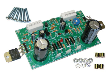
Velleman Discrete Power Amplifier 200W Kit K8060

You should pull all parts belonging to the amplifier section, mount the new PCB to the chassis floor, use the original powe supply (so when building the new power amp, do not fit the 2 large capacitors nor the 4 large diodes) , connect preamp out to power amp input and mount Darlingtons on original heat sinks, the MJ300x if still alive or the new TIP14x with some 4" long wires, similar to original construction.
Amp will work and sound just like the original.


 ) , pleast post the track side where the real damage is
Comment