Ad Widget

Collapse

Announcement

Collapse
No announcement yet.

Marshall Lead and Bass SS JMP 2195 issues

Collapse
X
 
  • Filter
  • Time
  • Show
Clear All
new posts

  • #16
    Originally posted by henter2017 View Post
    Thanks!

    I coudnt measure a couple of them as the resistor are right on the top of the markings but I got the rest

    This is the voltages with no load and the diodes D3 AND D4 lifted.

    2: 41V <--should be less than -100mV
    3: 17.39V <--should be around +700mV
    4: 23.75V <--should be less than -100mV
    5: 18.19V <--should be around +700mV
    6: 41.8V
    7: -7.38V <--should be around +700mV
    8: -40.5V
    9: -58mV <--should be a *positive* voltage
    10:41.1V
    11: -8.13V <--should be around +1200mV
    12: 9.80V <--should be around +700mV
    13: 64.4V <--should be around -1200mV
    15: 64.9V <--should be around +700mV
    16: 41.1V
    17: 24.38V
    18: 41.1V <--WTF??? should be around MINUS 41V
    Voltage measurements are SO fucked up and unlikely (wonīt use the word "impossible") that thereīs only a couple possible explanations, none of which helpīto remote control solve this reiddle (itīs way beyond plain "repair")

    in order of possibility:
    1) many tracks were destroyed, then were improperly reconstructed, so actual electrical circuit is nothig like the schematic.

    2) transistors were replaced, pinout did not match, in any case there is NO WAY a working BE junction has more that 700mV forward biased or from 5 to 8V reverse biased because it Zeners at that voltage.
    24 to 40V BE? NO WAY .

    3) in "red probe only" measurements where I asked the black probe to touch ground it either touched the -V rail or an ungrounded spot or ground leading to that point was cut.

    4) the expected -41V rail shows plus 41V ?????????

    please recheck all measurements and repost.

    Wonder why (1) and (14) could not be measured; if R18 or R34 legs were not accessible, any of them also connects "somewhere else" where probes cn be plced.

    Yes, some measurements are redundant, but I ask for all although I might derive about 1/3 of them from others, just as "checsum verification" , precisely because after gross PCB damage I can not trust parts are again connected as shown.

    Letīs try this once more, and if still wild differences, consider pulling all parts from the Power Amp and mounting a new one there; that power amp is as generic as can be, in fact itīs straight a Motorola datsheet application, no tricks such as mixed feedback , so any standard +/-40V amp will doexactly the same.

    One example which to boot uses Darlingtons :
    Velleman Discrete Power Amplifier 200W Kit K8060
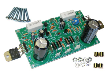

    You should pull all parts belonging to the amplifier section, mount the new PCB to the chassis floor, use the original powe supply (so when building the new power amp, do not fit the 2 large capacitors nor the 4 large diodes) , connect preamp out to power amp input and mount Darlingtons on original heat sinks, the MJ300x if still alive or the new TIP14x with some 4" long wires, similar to original construction.

    Amp will work and sound just like the original.
    Juan Manuel Fahey

    Comment


    • #17
      Thanks Juan Manuel,

      Acutally the - Rail is a typo, is -41V, but all measures taken in respect to ground, was with the black probe on the chassis fixed. So I think the power amp is literally tits up....
      I think best bet is putting a new power amp, I found this one local:

      LJM- MX50 SE Power amp Mono Amplifier Finished board | eBay

      How does it look?
      Would it be as easy as cutting from the schematic Preamp -B input and feeding it to the power amp, jumping the -V/-B and ground from the Rectifier bridge and chassis?

      Comment


      • #18
        Originally posted by henter2017 View Post
        Thanks Juan Manuel,

        Acutally the - Rail is a typo, is -41V, but all measures taken in respect to ground, was with the black probe on the chassis fixed. So I think the power amp is literally tits up....
        I think best bet is putting a new power amp, I found this one local:

        LJM- MX50 SE Power amp Mono Amplifier Finished board | eBay
        Looks like it might work, but personally Iīd spend the extra 8 GBP and buy the velleman from maplin which asks for 20 GBP ..... with free delivery so discount that.

        The point is although Iīm quite certain the Chinese one should work fine, we have no data whatsoever , I very much doubt they include the schematic, and in any possible future problem (or even now, on assembly) youīd be helpless.
        http://www.maplin.co.uk/p/velleman-2...lder-kit-l85bh


        Would it be as easy as cutting from the schematic Preamp -B input and feeding it to the power amp, jumping the -V/-B and ground from the Rectifier bridge and chassis?
        Basically yes: you connect ground/audio in/spk out/+V/-V/spk return from Marshall PCB to same points on the Velleman, plus you do not fit the 4 1N5404 supply diodes nor the 2 big filter caps; replace them with small 100uFx50V ones for local decoupling duty only.

        I suggest to remove al power amp parts between C14 and the output choke because old parts are still connected from +V and -V rails , you donīt need them and can cause big trouble.

        Just 5 minutes with soldering iron, vacuum pump and maybe a wire brush to remove useless parts, carbonized PCB areas and questionable tracks or pads.

        The Velleman amp uses a small transistor touching the heat sink for thermal compensation, you might drill a 1/4" or so hole in the heat sink and epoxy such transistor there; heatshrink wires leading to it.

        If using the EBay amp, youīll still have to mount power transistors to existing heatsink, Iīd ask them to send a schematic copy together with the board, "just in case".
        Juan Manuel Fahey

        Comment


        • #19
          Could I ask the background of this amp? Do you own it? Did it ever work for you?

          Replacing the power amp is possible, but is it really needed? This amp is not all that complex. Is the investment of the time and materials justified? What is a working amp really worth?

          Comment


          • #20
            the burned PCB was something that was fixed before, not by me, is all wired up from the back of the PCB
            Means the PCB , at least in the power section, is *destroyed*.
            Plus, have you read the measured voltages?
            There is a BIG difference between an amp which that just died and was brought in for repair "This amp is not all that complex." with which I agree, and "Jimmy 5 thumbs had a go at it with an oxyacetilene torch" .

            As of price, HK based Cyclops Electronics has them but also U$150 minimum order; UT Source has them at U$ 6.20 each, plus U$25 shipping to UK; Farnell has them for GBP4.44 each, I guess itīs over U$6 each, in any case there is no guarantee of success because all transistors are nuked and tracks canīt be trusted.

            Compare that to a guaranteed working amp for about 50% more than the replacement power transistors and it suddenly becomes attractive.

            As of
            What is a working amp really worth?
            , thatīs a valid question in "disposable USA" where even working stuff is junked all the time, plus "I can get another for peanuts at Craigslist or a garage sale" .

            For me, in this case replacing the power amp is not conceptually different to, say, replacing an STK power module.

            And again: please reread the BE voltages shown by those transistors, only way to get such values is to have internal chip to leg wires blown open, this is way worse than plain shorted transistors which is the usual case.
            To see it as a contractor:


            as a repair tech/contractor, would you plain rebuild those buildings, replacing bricks, tiles, plumbing, electrical conduits, repainting, etc. or would you .... ummmmmm .... just pick an empty piece of land a couple miles away and build NEW buildings?
            I shudder thinking about that PCB.
            Last edited by J M Fahey; 11-23-2016, 05:11 PM.
            Juan Manuel Fahey

            Comment


            • #21
              Come on, Juan. I appreciate the example, but can we please leave political comments in the section at the bottom of the forum?
              Education is what you're left with after you have forgotten what you have learned.

              Comment


              • #22
                I didn't mean to stir up anything here, all I wanted to know was a little background.

                I have not seen photos of the amp, so I have no idea of what condition the board is in, nor do I know the real technical abilities of any of the people that have worked on the amp now or previously. The power amp has maybe a dozen active devices so I would think that it wouldn't be that difficult for a trained tech to just fix it correctly.

                Good luck with the repair.

                Comment


                • #23
                  Sorry, I just wanted to post a graphical example on how I imagine the PCB condition, would have posted a charred abused PCB picture if I had one nearby but lacking that, my instant mind image was "Berlin 1945" ... but thatīs what showed up when I googled "bombed destroyed city" , specially because I wanted to compare repairing that amplifier to what a contractor would do if he had to choose between regular repairing "home damage" and "full rebuilding / replacing".

                  Will pull the political bit but I guess the unrepairable damage example is still valid.

                  Also wanted to point out that repair decisions are very different inside/outside USA, thatīs why I always insist on people stating where they are from.
                  Thanks.

                  PS: if you (or anybody) can link to some destroyed tracks and pads lifted PCB picture as an example I will gladly insert it instead
                  Juan Manuel Fahey

                  Comment


                  • #24
                    sorry for the delay in getting back, I was knocked down with a nasty flu for a while... Thanks for all the info, just to show how the 'burnt PCB" looks like I have attached a pic of it, there are several track repairs on the other side of the PCB too.. I will source the Verellen power amp and connect it to the preamp, I think it will be by far the simplest fix and not that expensive In my opinion, taking into account the time for rebuilding the original with this mess already there...

                    Comment


                    • #25
                      Originally posted by henter2017 View Post
                      just to show how the 'burnt PCB" looks like I have attached a pic of it, there are several track repairs on the other side of the PCB too
                      Oh, the top side in general does not look THAT bad (ouch!!! ) , pleast post the track side where the real damage is

                      A couple lifted pads or a section of burnt track is somewhat repairable with little bits of wire, but beyond certain point, even if possible (sort of), it becomes very unreliable.

                      And that, IF you get an amp just burnt but unmolested; once "somebody else" halfway tried to repair it and gave up, he usually leaves a destroyed messed PCB looking as if hit by a Tsunami.
                      Juan Manuel Fahey

                      Comment


                      • #26
                        Sure thing, here is a pic of the actual "repaired tracks"
                        A bit messy but cant really spot anything wrong, components have been tided and solder where the damage was...

                        https://www.dropbox.com/s/ur9woe501z...20pm.jpeg?dl=0

                        The grounding was redone as well, to a central star type but that probably was to reduce noise?

                        Few pots changed here and there, jack inputs wired floated from the board to probably alleviate stress on the PCB and bad connections... Im guessing im the 3rd or 4th person inside this amp at this point...

                        Comment


                        • #27
                          Originally posted by henter2017 View Post
                          Sure thing, here is a pic of the actual "repaired tracks"
                          A bit messy but cant really spot anything wrong, components have been tided and solder where the damage was...

                          https://www.dropbox.com/s/ur9woe501z...20pm.jpeg?dl=0

                          The grounding was redone as well, to a central star type but that probably was to reduce noise?

                          Few pots changed here and there, jack inputs wired floated from the board to probably alleviate stress on the PCB and bad connections... Im guessing im the 3rd or 4th person inside this amp at this point...


                          Pity that 95% of that PCB is fine, and IF that amp had been brought from death scene straight to your bench, then Yes, what 52 bill suggested, plain repiring it, would be the shortest path.
                          problem is that
                          Im guessing im the 3rd or 4th person inside this amp at this point...
                          so all track to original layout is lost for good.

                          Then substituting for something guaranteed working which can be fully swapped in 30 minutes becomes interesting.

                          Hey, even the cheaper EBay board will do IF you can mount the power transistors in the existing long narrow heatsink.
                          I guess it was designed to be bolted to a squarish vertically finned heatsink but if you can adapt it .... itīs up to you.
                          Juan Manuel Fahey

                          Comment


                          • #28
                            Originally posted by J M Fahey View Post
                            Then substituting for something guaranteed working which can be fully swapped in 30 minutes becomes interesting.
                            .
                            Definetly will give it a go with the new power amp board! and take of the power amp components of the old one to make things quicker, as I have checked and several transistors were substituted for alternatives and differ from the original schematic which makes the whole thing even messier...


                            Will report back! thanks again!

                            Comment


                            • #29
                              also luckily enough found the schematic for the ebay power amp online so will be sourcing this one, as is already built = less time, will clean up the old power amp section drill this board it, and heatsink the power transistors to the old disipator... and hopefully call it good, is an old amp, that definitely will be good to resurrect...

                              Click image for larger version

Name:	$_57.JPG
Views:	1
Size:	98.9 KB
ID:	844241

                              Comment


                              • #30
                                Thanks.
                                Just curious, on what page did you find it?
                                Didnīt find the schematic on the EBay page.
                                Juan Manuel Fahey

                                Comment

                                Working...
                                X