Originally posted by Jazz P Bass
View Post
Ad Widget
Collapse
Announcement
Collapse
No announcement yet.
Bandmaster AB763 low output w/ weird distortion (scope shots attached)
Collapse
X
-
This is the first Fender failed OT I've encountered, that's why I was really hesitant to believe that was the case. It was 022848, looked to be original.Originally posted by Leo_Gnardo View PostThe A6A, voted most likely to fail Fender OT. (Sound "Taps"). Oh well, replacements don't cost an awful lot, as long as you don't match brands with the PT.
Comment
-
That's actually refreshing. So many here jump straight to wanting to replace a transformer with little or no troubleshooting.Originally posted by waspclothes View PostThis is the first Fender failed OT I've encountered, that's why I was really hesitant to believe that was the case. It was 022848, looked to be original."I took a photo of my ohm meter... It didn't help." Enzo 8/20/22
Comment
-
I try to prove it's anything but the transformer, who wants that kind of bad news. OTOH if it's suspect, swapping in a known good one with 'gator clips is a fast test, and you don't even need the same exact transformer. If the power jumps up a bunch, you know what the bad news is.Originally posted by The Dude View PostThat's actually refreshing. So many here jump straight to wanting to replace a transformer with little or no troubleshooting.This isn't the future I signed up for.
Comment
-
Feeding AC on one side, reading it on the other, by itself does not prove a shorted turn OT, which is the typical failure.Means turns ratio 27.3 to 1 or impedance ratio of 744:1 , meaning PP impedance with an 8 ohms load of 5600 ohms (almost perfect book example) or half that with 4 ohms speaker; low but still usable.Input is 14.9 VRMS and output is .546 VRMS
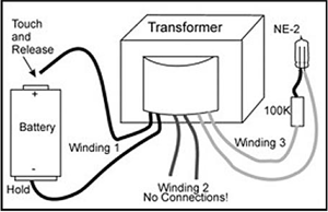
Proper shorted turn detection is by RG Keenīs neon bulb tester or plain replacement; unless you have a replacement OT on the bench the first one is faster and cheaper
https://www.premierguitar.com/articl...ormer-tester-1
 Juan Manuel Fahey
Comment
-
Hi Alex, I tested for DC voltage on the "other side" of the coupling caps while in circuit and they were all blocking DC so I left them in place. Is there anything else I should be testing with coupling capacitors?Originally posted by alexradium View Postare the coupling caps tested?
If its a vintage amp many times thats the culprit
New O.T. has been ordered and is on it's way, I will post an update when I get it in.
Comment
-
Okay the new O.T. came, swapped it out and got the same low output problem. Very confused on that one.. then I noticed the screen grid resistor was 47K instead of 470R! These looked orginal to me, I was never expecting to see a value off by 100. I even measured their resistance early on and probably just saw "47..." on the multimeter and didn't pay enough attention! After swapping those out, the amp was working fine.. so I put the old O.T. back in. So, lots of work for 2 resistors!Originally posted by waspclothes View PostHi Alex, I tested for DC voltage on the "other side" of the coupling caps while in circuit and they were all blocking DC so I left them in place. Is there anything else I should be testing with coupling capacitors?
New O.T. has been ordered and is on it's way, I will post an update when I get it in.
Here's a scopeshot of the output at full clipping:
1 (yellow) - 6L6 1 grid
2 (cyan) - 6L6 2 grid
3 (magenta) - P.I. input
4 (blue) - output to 8 ohm load.
Comment
-
Originally posted by waspclothes View PostOkay the new O.T. came, swapped it out and got the same low output problem. Very confused on that one.. then I noticed the screen grid resistor was 47K instead of 470R! These looked orginal to me, I was never expecting to see a value off by 100. I even measured their resistance early on and probably just saw "47..." on the multimeter and didn't pay enough attention! After swapping those out, the amp was working fine.. so I put the old O.T. back in. So, lots of work for 2 resistors!
Here's a scopeshot of the output at full clipping:
[ATTACH=CONFIG]43328[/ATTACH]
1 (yellow) - 6L6 1 grid
2 (cyan) - 6L6 2 grid
3 (magenta) - P.I. input
4 (blue) - output to 8 ohm load.
Posts #35 and #36 would have been very useful in solving this one
Comment
Comment