Ad Widget

Collapse

Announcement

Collapse
No announcement yet.

Super Reverb Replacement OT Wiring

Collapse
X
 
  • Filter
  • Time
  • Show
Clear All
new posts

  • #16
    They are windings, also generators, not speakers, loads.

    They generate power , not dissipate/sink it.

    Loads have resistance/impedance ; transformer taps do not

    To be more precise, they do have a little resistance: wire resistance, which if properly designed should be 1/10th to 1/20th the nominal impedance they are handling.

    Transformers by themselves do not have "impedance" by themselves , they reflect on one side what is present at the other side; they also "should" not dissipate any power, just fully pass tube power into speakers.

    After these different statements which in the long run mean the same:
    What properties are inherent in the two windings that result in 4 ohm ->parallel and 16 ohm->series?
    although we donīt daily use it in the OT area, maybe because of lazyness or tradition, is the concept that transformersī main job is to convert voltage, not impedance.

    That they also do it is just a happy byproduct of voltage conversion.

    Practical example of what is happening on that transformer:

    * each winding "should" be able to provide 12.6V RMS with amp just clipping.
    so
    *both windings in parallel (now itīs wired so): 12.6V available, into a 4 ohm load that means 12.6*12.6/4=160/4=40W RMS (I always round values to nearest significant one)
    and
    * both windings in series: 25.2V available so power is: 25.2*25.2/16=635/16=40W

    so now we understand why here we have only 4 or 16 ohm options, and not 8 (or 2 or any other), only voltages available are either 12.6 or 25.2 V RMS, period.

    While in a multi tapped winding such as the Hammond one we would have (always rounding values) :
    8.9 - 12.6 - 17.8 - 25.2 VAC which mean 40W RMS into 2 -4 - 8 - 16 ohms.
    Just do the Math yourself.

    As a side note, some expensive Hi Fi "universal" transformers have many (as in MANY) windings, both primary (they improve interleaving) and lots of secondary "voltage" windings, they are not even rated in ohms but each provides, say, 5V and 7V taps, and can be wired series parallel in multiple combinations so you can get practically any primary impedance into any secondary load and keeping excellent performance.
    Of course, that is expensive:
    this guy knows all about transformers, reading his entire site is well worth the time.
    No audiophool babble but good, solid, feet on the ground knowledge:
    index

    These old Geloso (Italy) PA amplifiers have each 4 secondary windings (so 8 terminals total), one can provide any impedance between 1.25 ohms and 500 ohms:


    Impedenze dīuscita: output impedances
    Linea ai morsetti: (speaker) line connected to terminals
    Unire tra loro i morsetti: join terminals together

    It also offers constant voltage, 100V lines, and if needed, some of those speaker outs are balanced.
    A truly universal amplifier.

    This one gives you any speaker combination between 1.8 and 16 ohms.
    Juan Manuel Fahey

    Comment


    • #17
      Holy crap, Jaun, this is awesome! I'll definitely study the info in your reply. So at first glance it appears to me that you based your calculations on the fact that the label on my torroidal OT indicated 4 or 16 ohm and that you happen to know that the Super Reverb is a 40 watt amp, is that safe to assume?

      Edit: Well I went and tried it out myself using my formula for power (P=(V*V)/R) plugging in 40 for P and 4 for R and indeed I got V = 12.6. So I answered my own question which was essentially, did you start with the premise that the amp is question is supposed to be 40 watts and work backward, so to speak.

      But I'm still unclear about why the two coils wired in the present manner constitute a parallel circuit. The fact that both leads of one coil are connected to a positive lug and both leads of the other coil are connected to a ground lug is throwing me off. And then what configuration would constitute series wiring in this case?
      Last edited by bobloblaws; 11-13-2017, 08:00 PM.

      Comment


      • #18
        Originally posted by bobloblaws View Post
        So at first glance it appears to me that you based your calculations on the fact that the label on my torroidal OT indicated 4 or 16 ohm and that you happen to know that the Super Reverb is a 40 watt amp, is that safe to assume?
        Edit: Well I went and tried it out myself using my formula for power (P=(V*V)/R) plugging in 40 for P and 4 for R and indeed I got V = 12.6. So I answered my own question which was essentially, did you start with the premise that the amp is question is supposed to be 40 watts and work backward, so to speak.
        Yes, that.
        "Educated guessing" (basing on having *some* of the data): yes.
        "Divination/Godīs Word" ... not in a Million years.
        But I'm still unclear about why the two coils wired in the present manner constitute a parallel circuit. The fact that both leads of one coil are connected to a positive lug and both leads of the other coil are connected to a ground lug is throwing me off. And then what configuration would constitute series wiring in this case?
        To avoid a special drawing, this PT one will do.
        Which is not *that* unrelated: an OT is a sophisticated PT, just that "Mains" comes from tube plates, in fact you have some 250/400VAC there, output voltage is 10/40 Volts and load is a speaker.
        Oh, and frequency is not fixed 50/60Hz but as wide ranging as 20Hz/20kHz.
        But the transformer "mechanism" is exactly the same.

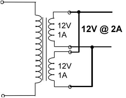
        Parallel connection of 2 separate but equal voltage windings


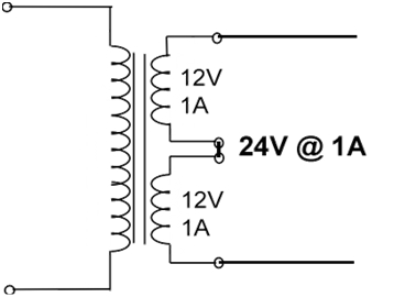
        Series connection of exact same windings:


        which also clearly shows the optimum impedance change:

        12V and 2 Amperes mean: 12/2=6 ohms.

        24V and 1 A mean : 24/1= 24 ohms.

        Notice the 2:1 voltage change meaning 4:1 impedance change.
        Juan Manuel Fahey

        Comment


        • #19
          Originally posted by J M Fahey View Post

          Parallel connection of 2 separate but equal voltage windings


          Series connection of exact same windings:
          Yes, this is what I thought, in fact I had drawn a couple of my own diagrams that were in effect equivalent to these. But the parallel diagram doesn't seem to jibe with the OT wiring on this amp, which we have been saying is wired parallel. For the sake of simplicity we can think of the two jacks as one since they are wired together in the traditional Fender configuration, as you have mentioned, with the tip lugs connected and the sleeve lugs connected through the chassis mounting. In your first diagram (parallel wiring), we can think of the two rightmost leads as one being connected to the tip lug and the other to the sleeve lug. In the diagram one end of the top winding is connected to tip and the other end to sleeve. Same for the bottom winding. Yet the photo shows that both ends of one winding (black/green) are connected to tip and both ends of the other winding are connected to sleeve. Can you see why I'm confused?

          Comment


          • #20
            Originally posted by bobloblaws View Post
            there is continuity (act. 0.5 ohm on my meter) between the black and white and the same between yellow and green. Infinite resistance between yellow and black and same between green and white.
            Originally posted by bobloblaws View Post
            Yet the photo shows that both ends of one winding (black/green) are connected to tip and both ends of the other winding are connected to sleeve. Can you see why I'm confused?
            You are saying 2 different things here. If you had continuity from black to white, then that is a winding.
            If the windings were shorted out as implied in the second quote, you would get no output.
            Originally posted by Enzo
            I have a sign in my shop that says, "Never think up reasons not to check something."


            Comment


            • #21
              Originally posted by bobloblaws View Post
              Yes, this is what I thought, in fact I had drawn a couple of my own diagrams that were in effect equivalent to these. But the parallel diagram doesn't seem to jibe with the OT wiring on this amp, which we have been saying is wired parallel. For the sake of simplicity we can think of the two jacks as one since they are wired together in the traditional Fender configuration, as you have mentioned, with the tip lugs connected and the sleeve lugs connected through the chassis mounting. In your first diagram (parallel wiring), we can think of the two rightmost leads as one being connected to the tip lug and the other to the sleeve lug. In the diagram one end of the top winding is connected to tip and the other end to sleeve. Same for the bottom winding. Yet the photo shows that both ends of one winding (black/green) are connected to tip and both ends of the other winding are connected to sleeve. Can you see why I'm confused?
              You "see" it wrong.
              One winding goes from Black to White ; the other goes from Green to Yellow .
              Black (hot end from one winding) goes to tip together with Green, the hot end from the other winding.

              White (cold end from one winding) goes to tip together with Yellow, the cold end from the other winding.

              Which you had already detected:
              Quote Originally Posted by bobloblaws View Post
              there is continuity (act. 0.5 ohm on my meter) between the black and white
              So Black/White are opposite ends of the same winding.
              and the same between yellow and green.
              So Green/Yellow are opposite ends of the same winding.
              Infinite resistance between yellow and black and same between green and white.
              So Black+White and Green+Yellow define different windings.

              EDIT: now that I think of it, *maybe* you expected to measure 4 ohms between Black and White or Green and Yellow?
              It does not work that way.
              Last edited by J M Fahey; 11-14-2017, 08:15 PM.
              Juan Manuel Fahey

              Comment


              • #22
                JM and G1, I stand corrected, for some reason I was thinking I had earlier identified green and black as one winding and white and yellow as the other. It all adds up now, thanks!

                - BL

                Comment

                Working...
                X