Ad Widget

Collapse

Announcement

Collapse
No announcement yet.

Peavey VTM - from 6L6 to EL34

Collapse
X
 
  • Filter
  • Time
  • Show
Clear All
new posts

  • Peavey VTM - from 6L6 to EL34

    Hey all. I've been modding my VTM quite a bit the last few months.
    I think it's finally time for me to make the switch to EL34s.

    Here's a list of specs on the PT that I got from a Peavey representative.
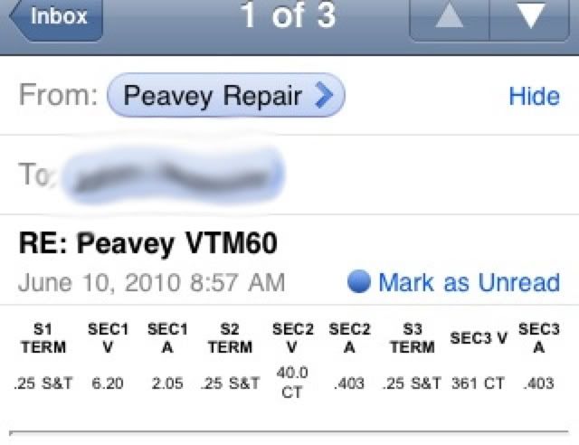

    Not really what all that means....
    But I've heard of people modding their VTMs to take EL34s and they never talk about changing the PT.

    Also, I've nodded mine to have a bias pot. Right now it's at 33mA.

    VTM schematic:
    http://www.schematicheaven.com/newam...vy_vtm_120.pdf

    Let me know if you need to know anything else.

  • #2
    The power transformer will be fine. There are other far more important issues in such a conversion.

    The circuit board for the output tubes is designed for 6L6s. 6L6 doesn;t use pin 1, so for board layout convenience, they ran the plate leads across puns 1. But on EL34, pin 1 must be connected to pin 8. This is not technically daunting, but MUST be converted. Once done, 6L6s will still work fine in the sockets.

    The bias needs of the EL34 will be very different, so the bias supply will require modification.
    Education is what you're left with after you have forgotten what you have learned.

    Comment


    • #3
      So pin 1 needs to go to ground? That's where pin 8 goes. 1 is also currently connected to 3? I just leave that?


      What needs to be changed in the power supply?

      Comment


      • #4
        See, I was looking at this....
        6L6 to EL34 Mod

        But was a little confused since I don't have the parts mentioned in step 1 & 2 that they mention.

        Comment


        • #5
          You have them, but the description in your link is for point to point wired amps like a Fender Twin.

          You need to understand what you are doing. Pin 3 of the power tubes is the plate - that is where about 480 volts sits. If you ground that, fuses will blow. You have to rewire pin 1 ro pin 8 or to ground, but the problem is that the 480v plate lead runs right over pin 1. SO one must cut traces and run wires to reconfigur this circuit. Pin 3 must remain wired to the output transformer and the flyback diodes. Pin 1 must be separated from those things and routed to pin 8.

          And yes, you would want to change those screen resistors.

          The bias supply is not as simple a change as he suggests. You would need to change a couple resistors and add a pot.
          Education is what you're left with after you have forgotten what you have learned.

          Comment


          • #6
            Yeah that's what I figured. Not a problem, I've done PCB corrections, like for adding the 1 ohm resistor to check the bias.

            I've already modded the power supply board and corrected the voltage divider. I think it was R8 and R9. It's how I got it to bias hotter.

            And I meant that the VTM doesn't have a resistor between pin 1 and 5, or between 4 and 6.

            Comment


            • #7
              How the stock amp is running 4x6L6GC and 4x12AX7 with a 2A heater transformer secondary? To me it adds up to 5A, and with EL34 is 8A...

              Comment


              • #8
                Sorry, the schematic/layout is for both the VTM60 and 130. I have the VTM60.

                Comment


                • #9
                  Those resistors are not physically soldered to those socket pins, you are right. IN an amp like the Fender, since pins 1 and 6 are not used, they used the socket pins as handy solder points to mount the resistors rather than have them hanging in the air. But pins 4 and 5 are grids, and the amp does have the resistors for those grids on the pc board near the socket. SO it is in that sense you have them.
                  Education is what you're left with after you have forgotten what you have learned.

                  Comment


                  • #10
                    Okay, so to recap....
                    R7 should be changes to 5.6K?
                    R8 to 1k to 1.5k?
                    Pin 1 need to have it's trace cut and connected to Pin 8.

                    Going off this:
                    http://mhuss.com/MyJCM/JCM800_2204.gif

                    Is that everything?

                    Comment


                    • #11
                      You have to cut the pins 1 free and connect them to ground/pin8. But you also must maintian the circuits to the pins 3 and the flyback diodes. SO that means additional trace cutting and rerouting/wiring.

                      R7?
                      Education is what you're left with after you have forgotten what you have learned.

                      Comment


                      • #12
                        Yeah, I'm aware I'll have to jumper a few points to keep pin 3 correct.

                        Do I not change the 47K resistor? Like I said, was going by a JCM800 schem there.
                        But I DO also change the 100 ohm resistor on pin 4 for a 1.5K, right?

                        Is that everything?

                        Comment


                        • #13
                          Well one has to wonder why we keep looking at the Marshall schematic when we are working on the Peavey.

                          Marshall derived their bias supply from the high voltage winding of the power transformer, Peavey has a low voltage winding for the purpose.

                          The 47k resistor on the power supply board is R8, not R7, so it is confusing when we refer to R7. And then we refer to R8 as 1.5k, which doesn;t make sense in the bias supply. There is an R8 on the power tube board, and it is one of four screen resistors, so I guess that is what you mean there. But on the VTM60 I think only V2 and V3 are installed, and thus only screen resistors R4 and R6 would be in use.

                          Yes, you will have to change the 47k or make it variable, but that will do nothing until you also change the 470 ohm R9 to something like 3k or thereabouts. It isnl;t the parts, it is the circuit, and this circuit is a voltage divider. And that voltage divider won't have much to divide with with 470 ohms on top.
                          Education is what you're left with after you have forgotten what you have learned.

                          Comment


                          • #14
                            Hm, okay.
                            Sorry, I was switching between the versions because I was under the impression they were pretty close relatives, didn't realize the power supply section would affect the resistors there so much.
                            And yeah, I wasn't sure which screen resistors would be on my board, TBH. Haha

                            I was just going to make sense of it the next time I checked it out.
                            Once I change it closer to 3K, how will I know what to change the 47K for? What numbers should I be measuring and working off of?

                            Comment


                            • #15
                              Make the 47k variable. A 50k pot wired as a variable resistor perhaps. Or better, something like a 22k resistor and a 25k pot in series. That would be the equivalent of a 47k that could dial down to about half of itself.
                              Education is what you're left with after you have forgotten what you have learned.

                              Comment

                              Working...
                              X