Ad Widget

Collapse

Announcement

Collapse
No announcement yet.

FET as cathode follower...Sorry. Not for valve fanatics...

Collapse
X
 
  • Filter
  • Time
  • Show
Clear All
new posts

  • FET as cathode follower...Sorry. Not for valve fanatics...

    Hi!

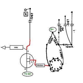
    I would like to know if my lyout for this mod is correct.

    http://www.harpamps.com/micKcircuits...-follower.html

    Only the most relevant conections are shown...


    Best regards from spain
  • #2
    Off the top of my head I'd say no.
    The FET source should not be connected to the B+ from the plate load resistor.
    The 100K plate load needs to be connected to lug 6 and if you want the blocking cap, the source would be connected to the .047 cap while that same cap is disconnected from the 100K plate load resistor.
    I've always used a big power IRF MOSFET not a signal FET, and I always use a 100 ohm resistor on the gate lead from the plate of the triode.
    This is all explained well at RG's GEO site.
    http://www.geofex.com/Article_Folder...osfetfolly.htm
    Attached Files
    Bruce

    Mission Amps
    Denver, CO. 80022
    www.missionamps.com
    303-955-2412

    Comment


    • #3
      ..... Is this ok?


      I´m gonna use a IRF830. (hard to find a IRF820 in my TV local tech)

      This mod is for the Normal channel of a Fender blackface, with reverb and tremolo in both channels. For this mod, i send the Normal channel signal to the reverb mixing resistor and cap (3.3M/10pf)....

      Could i avoid the .47 coupling cap?

      Comment


      • #4
        Except you are talking about a different circuit, for a different use, what you drew, including an IRF830, is exactly how I do it in the Aurora amp, which only has two preamp tubes.
        Bruce

        Mission Amps
        Denver, CO. 80022
        www.missionamps.com
        303-955-2412

        Comment


        • #5
          Why would you insert a CF at that point in he circuit?

          Thanks,
          Jelle

          Comment


          • #6
            Originally posted by Jelle View Post
            Why would you insert a CF at that point in he circuit?

            Thanks,
            Jelle
            I,m modding the normal channel of my Guyatone ga1050 (Bandmaster combo clon)
            Voltage droped in V1 and tone stack stack changes done.....
            Now i,m looking for a little more..... crunch...

            Comment


            • #7
              Originally posted by Bruce / Mission Amps View Post
              Except you are talking about a different circuit, for a different use, what you drew, including an IRF830, is exactly how I do it in the Aurora amp, which only has two preamp tubes.
              And what do you use it for? If i could make it swichtable it would perfect...

              Comment


              • #8
                Sorry, the following is maybe a little bit off topic.
                I don't remember where I got this FET buffer schematic from but it looks exactly like MESA's DR FX loop buffer. I tried it but it after a regular TS because I didn't want to use an extra tube but at higher levels it was clipping. Does in this case the cathode resistor have the same influence as in a regular CF - less R more distortion and vice versa and what is the range of its value?
                Attached Files

                Comment


                • #9
                  Originally posted by Gregg View Post
                  ....Does in this case the cathode resistor have the same influence as in a regular CF - less R more distortion and vice versa and what is the range of its value?

                  Yes..mmmm maybe changing the 33k one for a 56k you solved the problem...

                  Another of-topic... Wich values do you finaly chose for the gate resistors?
                  Last edited by chocopower; 06-26-2007, 07:51 AM.

                  Comment


                  • #10
                    Originally posted by chocopower View Post
                    And what do you use it for?...
                    EXTREMELY low zed to drive a tone stack and it offers virtually zero distortion.
                    Bruce

                    Mission Amps
                    Denver, CO. 80022
                    www.missionamps.com
                    303-955-2412

                    Comment


                    • #11
                      Wich values do you finaly chose for the gate resistors?
                      Actually I didn't experiment too much and used 1M.
                      I expect some comments from R.G. on this whole subject.

                      Comment


                      • #12
                        Originally posted by Bruce / Mission Amps View Post
                        EXTREMELY low zed to drive a tone stack and it offers virtually zero distortion.
                        so...... can this mod increase gain in V1 or is just a dumb change?

                        Comment


                        • #13
                          Originally posted by Gregg View Post
                          Actually I didn't experiment too much and used 1M.
                          I expect some comments from R.G. on this whole subject.
                          I guess I'd better reply then...

                          The MOSFET source follower replacement for a CF is a handy way to put in a very low impedance buffer/follower. The input side offers a very high impedance to whatever drives it, and the output is very low impedance, much lower than a CF.

                          On the input side, the thing suffers only from having a high gate-source capacitance, which is mitigated by the device running with 100% negative feedback as a follower. The follower connection prevents the gate-source capacitance from overloading the device it's buffering and makes the whole thing work. You're good to go up to the top end of the audio range with a 12AX7 driving a power MOSFET. The easiest way to do this is to collect the MOSFET gate directly to the triode plate.

                          If you don't have a plate handy to connect it to, then you need bias resistors, as in the thumbnail. The input impedance for low and mid audio range is essentially the parallel combination of the two biasing resistors, so 1/2M for the 1M resistors, 1.6M for the two 3.3Ms.

                          The output impedance is low, off the charts low. The IRF8xx transistors have a transconductance of about 1/2 A per volt on the gate and a threshold voltage of 2-4V. Once you get above the threshold gate-source voltage, the device conducts about 0.5A/V. So in a tube application with tens of volts available to drive the gate-source, the thing is always running just barely cracked open. A heavy load on the source can be driven easily, as long as it's heavy pulling it up.

                          The pull down is all done by the load resistor, which is the origin of the distortion.

                          If you really want to drive a heavy load with a CF in a tube amp, concoct a constant-current source load from another MOSFET to replace the source resistor. Now the load can be actively pulled down by a MOSFET as well as up, and you can probably drive a speaker directly from the MOSFETs. Heck, no probably about it. It will drive amps directly from the source follower. This is one way to make a solid state audio power amp.

                          However, for use in a tube amp, it's probably overkill.

                          Running the source resistor up makes it easier for the preceeding stage to drive the high gate-source capacitor at all frequencies and I think that's what happened for you.

                          The IRF800 series is not the only one to use. There are some dandy fine devices available from Zetex. The ZVN0545A comes in a TO-92 equivalent package and is rated for 450V, 90 ma, and 0.7W.

                          You have to be careful not to bias it at too high a current and exceed the power rating, but it's input capacitance gate-source is only 55pF, so it can be driven by a typical 12AX7 plate WITHOUT source feedback assist to over 17kHz. In the SF setup, it's good to far beyond audio. There are also complementary P-channel devices (e.g. ZVP0545A) that could be used to make a complementary MOSFET follower that would be a massive driver for any load you'd like in a tube amp.
                          Amazing!! Who would ever have guessed that someone who villified the evil rich people would begin happily accepting their millions in speaking fees!

                          Oh, wait! That sounds familiar, somehow.

                          Comment


                          • #14
                            ufff....... to much to my poor inglish vocabulary....

                            so..... could this work?

                            Comment


                            • #15
                              Originally posted by chocopower View Post
                              ufff....... to much to my poor inglish vocabulary....

                              so..... could this work?

                              In simple terms, YES.
                              Bruce

                              Mission Amps
                              Denver, CO. 80022
                              www.missionamps.com
                              303-955-2412

                              Comment

                              Working...
                              X