Announcement

Collapse
No announcement yet.

Power supply connundrum.

Collapse
X
 
  • Filter
  • Time
  • Show
Clear All
new posts

  • Power supply connundrum.

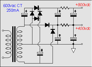
    I've got a prototype amp built which uses a Marshall 1987X preamp and PI and some output tubes which only want to see about 250V on their plates, but require almost as much grid drive voltage as a normal EL 34 amp to clip. At the moment, I've got a transformer which puts out almost exactly 250V rectified B+ (two diode, full wave with a CT) at and I have a smaller power supply "stacked" on top of that to get the preamp/PI voltages up where they'd be in a stock 1987X. It works OK and sounds quite nice, but I'm looking for a more elegant solution.

    Here are my thoughts:

    1.) Just design the power supply to start with a 400V B+ and regulate it down for the output tubes. (Too complicated, might make the supply too stiff?)

    2.) try to redesign the preamp and PI to work acceptably well at lower voltages. (With the main B+ at 250V, after the add'l filtering, I doubt I'd have much more than 200-220V B+ for the PI.)

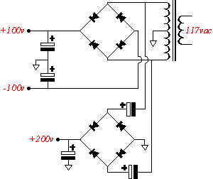
    3.) Add a second pair of diodes & cap to the power supply and generate a B- rail. Add add'l R-C filtering stages to get the B- down to -150V or so. Run my preamp and PI cathode/tail resistors to this supply. Would this work?

    4.) Derive the preamp voltages from a voltage doubler which can share the main B+ transformer winding with the power amp? (possible?)

    5.) Find or commission a transformer with multiple secondary windings which will suit my needs. Where??

    6.) Leave it kluged the way it is with two power transformers.

    Your opinions, gents?

    Nathan

  • #2
    I have another idea. I only know the basic power supplies so I'm not sure how this could be done but... Maybe you could just use the 250V PT and derive a voltage doubler from the rectified B+ to feed the PI and preamp. A voltage doubler would provide less current capacity but it shouldn't be a problem for the PI and preamp. I think this could be done because I've seen single line feed bias circuits that are voltage doubled. But I can't remember how it was done.

    Chuck
    "Take two placebos, works twice as well." Enzo

    "Now get off my lawn with your silicooties and boom-chucka speakers and computers masquerading as amplifiers" Justin Thomas

    "If you're not interested in opinions and the experience of others, why even start a thread?
    You can't just expect consent." Helmholtz

    Comment


    • #3
      Two thoughts, but I don't know if they'll add up to much because I'm still new at this.

      Thinking out loud here. What if you use series caps and pulled the power tube plate supply from the juncture of the two caps? Take two 350v caps and tweak the balancing resistors so that the series node of the caps was 250v. Pull the preamp from the top and the plate and screen from the node.

      4.) Derive the preamp voltages from a voltage doubler which can share the main B+ transformer winding with the power amp? (possible?)
      I remember reading somewhere that an amp (Fender?) used a similar arrangement but the doubler was driving the power tubes which to me seems like a more demanding application than driving the preamp. Since you've already got the iron, the preamp pulls very little current which is good for a voltage multiplier, and building a multiplier is fairly cheap/easy, I'd at least audition this one. If you don't like it, you're out a grand total of about 10-20 bucks. The only thing that might be an issue is that a voltage doubler doesn't smooth as well as a full wave rectifier,so you will have more ripple than you currently have. This could make a difference in the noise, or it could not.
      -Mike

      Comment


      • #4
        What exactly are the voltages you need? 250VDC and... something higher? Are these set in stone? (i.e an optimized design?)

        I've been looking at some multitap control transformers recently

        they're cheap and when wired backwards will produce many useful voltages, no heater or bias tap but what do you want for $20...there are multitap tube transformers too, a little more expensive though

        Comment


        • #5
          Why don;t you tell us what the tubes are?

          Two thoughts:

          1. Just because the tube manual says 250v doesn't mean that is all you can put on the tubes. Remember, Leo Fender ran 6V6s in many of his amps at as much as 100v over the book voltages. Your mystery tube mught be happy as a clam at higher voltage.

          It is not overvoltage that kills tubes, it is over-dissipation.

          2. You could run the power tubes with cathode bias. SInce the tube is sensitive to voltage across the tube, NOT voltage absolute with respect to ground, the entirety of the cathode generated bias voltage could be added to your B+ total.
          Education is what you're left with after you have forgotten what you have learned.

          Comment


          • #6
            I'm leaning towards trying a voltage doubler, simply because I have a nice existing transformer which puts out a B+ of 250VDC.

            Basically, I'm trying to get +250 and a well filtered 340V node for the PI. (So I'll need to start with perhaps >360V prior to an R-C filter stage.)


            Enzo: You have a good point about getting away with exceeding the max spec sheet voltages, but as you mentioned, you don't want to exceed the plate dissipation- I don't want to have to bias colder. I'm already running cathode bias. I also don't want to get more power out of this thing, and I'm happy with how it sounds at 250V- hence my dilemma.

            nathan

            Comment


            • #7
              Originally posted by tedmich View Post
              What exactly are the voltages you need? 250VDC and... something higher? Are these set in stone? (i.e an optimized design?)

              I've been looking at some multitap control transformers recently

              they're cheap and when wired backwards will produce many useful voltages, no heater or bias tap but what do you want for $20...there are multitap tube transformers too, a little more expensive though
              Who supplies these control Xmers? The voltages wouldn't be quite right for this project, but it seems like a nice range of voltages for other tube amp applications.

              Comment


              • #8
                Originally posted by octal View Post
                Who supplies these control Xmers? The voltages wouldn't be quite right for this project, but it seems like a nice range of voltages for other tube amp applications.
                Sola Hevi Duty has some neat ones, and on the Ebay often, with flat rate $10 shipping (they're HEVI) check these:

                Group 4 SBE encapsulated, just about right for 2 x EL84 at 400VDC


                the Group 3 SBE is very flexible:

                these are big and crude, they ain't no Lundahls! At least the windings are Cu, some china ones are Al...ugh

                this 20lb badboy is $39 at alltronics.com
                and puts out ~2A at 288VAC which should be AOK for my 6 channel Bravo...

                Comment


                • #9
                  Originally posted by octal View Post
                  I'm leaning towards trying a voltage doubler, simply because I have a nice existing transformer which puts out a B+ of 250VDC.

                  Basically, I'm trying to get +250 and a well filtered 340V node for the PI. (So I'll need to start with perhaps >360V prior to an R-C filter stage.)
                  With a centre-tapped PT it's easy to get extra rail voltages, including voltage doubled or even tripled, depending on where you reference you brigne rectifier to: http://www.tubecad.com/january2000/page16.html

                  Comment


                  • #10
                    Originally posted by Merlinb View Post
                    With a centre-tapped PT it's easy to get extra rail voltages, including voltage doubled or even tripled, depending on where you reference you brigne rectifier to: http://www.tubecad.com/january2000/page16.html

                    Merlin is right, the Duncan PSUD II app has a voltage doubler model built in. Its much easier to double it up and you can drop a few volts if needed with resistance or more with a zener, or zener/mosfet combo, (or you could go crazy with a Swenson/Pimm HV regulator but its best at +60vdc drop)

                    Comment


                    • #11
                      D'oh. It's so simple. All I need to do is wire a bridge rectifier across the output of the PT. Ground the - output of the bridge rectifier, have two filter caps stacked in series with the CT of the power transformer going to the middle junction of the filter caps. I'll have +250 DC at the center tap for the outputs, and +500 at the top, which I can R-C filter down to get the voltage my preamp needs.

                      Nathan

                      Comment


                      • #12
                        Set it up that way tonight and it works great. Thanks to everyone for your thoughts and suggestions.

                        Comment


                        • #13
                          If I'm reading it right, that's similar to what I suggested in my post. What I'm confused about though is why you have to put the CT at the series node of the caps. What does this provide?
                          -Mike

                          Comment


                          • #14
                            If you just had two series caps with balancing resistors across the entire, non centertapped X-mer winding, all of the current would have to go through the balancing resistors. Yes, you could use low value balancing resistors, but they would dissipate a ton of power. The centertap keeps the voltages balanced regardless of current draw, with no need for balancing resistors.

                            Think of it as a bipolar power supply, like in a solid state amp; plus and minus 250. You're just grounding the -250 output. The centertap will be 250v more than that, and the "+250" output will be at +500 (relative to ground, which would have been -250.) I'm not sure that's the best explanation, but it does work fine! Time for bed.

                            Comment


                            • #15
                              Thank you for the explanation, it makes perfect sense. I was wandering how current was going to be supplied to the series node when I wrote out my description - and now I know.
                              -Mike

                              Comment

                              Working...
                              X