 Tweet
Tweet
Hi,
I've just got a PT from a Peavey Classic 30 and I'm trying to use it in a 2 x 6l6, 2 x 12ax7, 2 x 12at7 project
Unfortunately, the classic 30 runs its power tubes (4 x el34) in series... as such the power transformer has a 32Vac tap for the filaments.
I am not very well versed with the theory in this area, but could I run the following?:
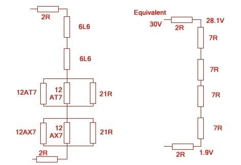
1 x 6L6 - 900mA, 6.3V
1 x 6L6 - 900mA, 6.3V
2 x 12AT7 - 2 x 450mA, 6.3V
2 x 12AX7 + 300mA dummy load - 3 x 300mA, 6.3V
Each section requires 900mA @ 6.3V
The classic 30 uses 3 ohm resistors, then 25.2V drop across 4 x EL84s.. leaving what I presume to be 6.3V for the preamp tubes in parallel (however, there are 3 of them, which would draw 900mA, does this mean they're slightly current starved? I believe an EL84 is rated at 750mA or thereabouts)
Any help with my confusion would be much appreciated,
Harry
I've just got a PT from a Peavey Classic 30 and I'm trying to use it in a 2 x 6l6, 2 x 12ax7, 2 x 12at7 project
Unfortunately, the classic 30 runs its power tubes (4 x el34) in series... as such the power transformer has a 32Vac tap for the filaments.
I am not very well versed with the theory in this area, but could I run the following?:
1 x 6L6 - 900mA, 6.3V
1 x 6L6 - 900mA, 6.3V
2 x 12AT7 - 2 x 450mA, 6.3V
2 x 12AX7 + 300mA dummy load - 3 x 300mA, 6.3V
Each section requires 900mA @ 6.3V
The classic 30 uses 3 ohm resistors, then 25.2V drop across 4 x EL84s.. leaving what I presume to be 6.3V for the preamp tubes in parallel (however, there are 3 of them, which would draw 900mA, does this mean they're slightly current starved? I believe an EL84 is rated at 750mA or thereabouts)
Any help with my confusion would be much appreciated,
Harry
Comment