Ad Widget

Collapse

Announcement

Collapse
No announcement yet.

Series / Parallel Heater Combinations

Collapse
X
 
  • Filter
  • Time
  • Show
Clear All
new posts

  • Series / Parallel Heater Combinations

    Hi,

    I've just got a PT from a Peavey Classic 30 and I'm trying to use it in a 2 x 6l6, 2 x 12ax7, 2 x 12at7 project

    Unfortunately, the classic 30 runs its power tubes (4 x el34) in series... as such the power transformer has a 32Vac tap for the filaments.

    I am not very well versed with the theory in this area, but could I run the following?:

    1 x 6L6 - 900mA, 6.3V
    1 x 6L6 - 900mA, 6.3V
    2 x 12AT7 - 2 x 450mA, 6.3V
    2 x 12AX7 + 300mA dummy load - 3 x 300mA, 6.3V


    Each section requires 900mA @ 6.3V


    The classic 30 uses 3 ohm resistors, then 25.2V drop across 4 x EL84s.. leaving what I presume to be 6.3V for the preamp tubes in parallel (however, there are 3 of them, which would draw 900mA, does this mean they're slightly current starved? I believe an EL84 is rated at 750mA or thereabouts)

    Any help with my confusion would be much appreciated,

    Harry
  • #2
    12AT7s (and 12AX7s) have 300mA filaments @ 6.3V, or 150mA @ 12.6V.

    So I would say rectify and filter the heater winding in the same way as a C30 and use a voltage divider to get the right series voltage, being careful to calculate the divider so as not to lose more than the required current for all the tubes at the knee of the divider. JM2CW
    Last edited by tubeswell; 08-10-2009, 03:52 AM.
    Building a better world (one tube amp at a time)

    "I have never had to invoke a formula to fight oscillation in a guitar amp."- Enzo

    Comment


    • #3
      Looks pretty good to me!

      So, just so I've understood, you would recommend

      Rectifying to dc (get maybe 38, 39V)

      Stepping that down to 25.2V *

      Using 25.2V for 4 preamp tubes in series

      Stepping the aforementioned 25.2V down to 12.6V *

      Then using the 12.6 V for the 6L6s wired in series?


      * Using a voltage divider with reasonably high resistance so as to not lose too much current to heat dissipation in the resistors.

      Comment


      • #4
        I knew I'd forgotten something... I was planning to use an SRPP to drive a medium-impedance reverb tank as per Merlin's site (and maybe his book when it arrives!)

        This circuit calls for the heaters to be d.c. elevated. Is that out of the question now?

        Comment


        • #5
          C30 uses EL84, not EL34.

          Without referring to Merlin's book, I assume he has the heaters elevated for hum reduction. if you are running the heaters on DC already, elevating them does nothing.

          I don;t think you have analyzed the Peavey circuit very accurately. And you cannot just add up tube rated voltages and combine them thinking the voltage across the tube will be what it wants.

          The four EL84 power tubes are in series across roughly 25 volts of AC, not DC. The two 3 ohm resistors are there to trim the voltage a little.

          How did you determine that 32VAC figure? if you measured the transformer unloaded, then that explains the high reading.


          The C30 rectifies that AC to make 36VDC. The three 12AX7s in that amp are wired in series across that - three 12v heaters makes 36v. It is nice quiet DC. The power tubes are running on AC. there is no 6v left over from anything.

          I didn;t understand all that seires current draw. at 12v, one 12AX7 draws 150ma. Two 12AX7s in series also draws 150ma, but it requires 24v to do it. Currents are equal in a series circuit. Four of them in series still draws 150ma, but would require 48v. The same process holds if you want to run them as 6v heaters. Then they draw 300ma. Doesn't matter how many are in series, the current will stay the same, but you will have to add another 12v or 6v for each tube you add.

          You cannot run a 6L6 and a 12AX7 in series and expect the voltages to equalize. They are not zener diodes, they don;t establish a set voltage drop. They act like resistors in series, and so we apply Ohm's Law to them.

          Taking a 6L6 as 6.3V at .9A, we can say they have a hot resistance of about 7 ohms. Wire a 12AX7 for 6v, and we find 6.3v at .3A shows a hot resistance of 21 ohms. Put the two in series and apply 12v across the pair, and you will not see 6v across each one. You will see about 3v across the 6L6 and about 9 across your 12AX7. And that 12AX7 will be darn bright. At least for a while.

          You can;t use high resistances in a voltage divider for high current loads. ANy current for the tube heater has to flow through those high resistances. And Ohm's Law once again will tell you that you can't drag 2.4 amps of 6v through a 10k resistor. Yu can add a series resistance to your load - as PV did with the pair of 3 ohmers.

          To do this the way you are suggesting will require you jumping through a lot of hoops to get there. May I suggest getting a different PT for this project. Or if you want to keep this one, add a heater transformer - a plain old vanilla 6VAC supply. Then use the 25v winding on the Peavey part for a bias supply, a relay supply, and a supply for any solid state circuits.
          Education is what you're left with after you have forgotten what you have learned.

          Comment


          • #6
            Thank you, Enzo. This answers a lot of questions I had.

            Back to the drawing board..

            Comment


            • #7
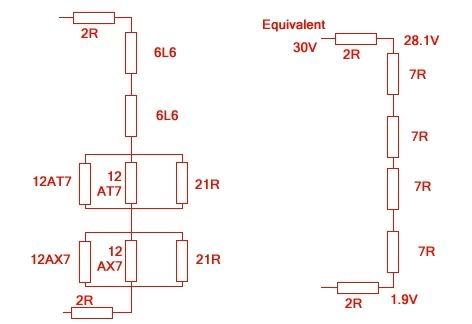
              How about this then:


              If each 12AX7 represents 21R, then three of these in parallel would equal 7R.

              The tubes would draw 900mA of current. In the Peavey, this is 750mA, but then you have the 150mA for the preamp tubes on top of that.

              From the C30 schematic, I calculated the loaded AC supply to be just under 30V. Each EL84 represents 8.5ohms. Four of these would be 34 ohms. Using with the pair of 3 ohm resistors lowers to about 25.5V (assuming 30Vac secondary)

              My circuit elements are 7ohms each, giving 28 ohms total. Therefore I need a pair of 2 ohm resistors to lower the 30V to around 25.5V.

              Are there any holes in this theory?
              Last edited by harry; 08-10-2009, 08:18 AM. Reason: Elucidation

              Comment


              • #8
                I looked at the output of the bridge rectifier, specified as 36VDC. It takes about 25VAC to make 36VDC when rectified and filtered.

                Connect some mains power to your transformer, slap a 1 amp load on the winding, and see what the AC voltage drops to.

                I don't know, maybe you would get away with it, it just seems so convoluted to me. Plus you now have that pair of 21 ohm resistors dissipating about 1.7 watt apiece. SO a 5 watt resistor ought to be specified. More heat under the chassis. I also concern myself with the warm up phase. How long will it take for the voltages to settle in your string.
                Education is what you're left with after you have forgotten what you have learned.

                Comment


                • #9
                  That's a good point, I can't imagine it will do the tubes any good on startup. It depends how the different tube types behave I suppose. If they turn on at similar rates, hopefully any voltage going too high will be temporary.

                  I'm thinking about replacing the 2 resistors with another two preamp tubes. Seems a shame to waste them. I will make sure they're used in a way that doesn't draw too much B+ current... I don't know what the HT winding is good for.

                  Comment


                  • #10
                    Originally posted by harry View Post
                    That's a good point, I can't imagine it will do the tubes any good on startup. It depends how the different tube types behave I suppose. If they turn on at similar rates, hopefully any voltage going too high will be temporary.
                    You can always replace the 21 ohm resistors with 6V, 3W zener diodes.

                    Also, for the SRPP you really should elevate to avoid exceeding the heater-cathode breakdown voltage.

                    Comment


                    • #11
                      Hadn't thought of that, thanks Merlin.

                      I'm worried about the implications of trying to raise one "branch" of the heaters. Obviously I can't apply it to the start of the heater chain, as the DC offset will be stepped down as well. Presumably I can add DC to one branch only by isolating it from the heater chain with a capacitor.. just wondering what effect this would have on startup!

                      Comment


                      • #12
                        You are talking about using AC heaters right? In which case you can inject your DC elevation voltage literally anywhere along the heater chain. At one end, in the middle, artificial centre tap, part way along...wherever, as long as the heater supply is not grounded anywhere of course.

                        Comment


                        • #13
                          ..!!!

                          of course

                          Sometimes I forget the most basic things...

                          Thanks Merlin.

                          Comment

                          Working...
                          X