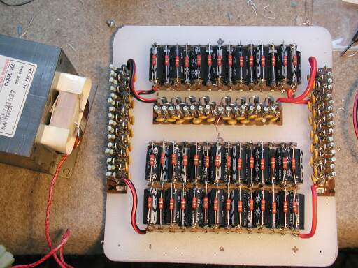
I'm confused on something and could use an explanation. I've seen this configuration in many schems, but I always figured the parallel caps were just for snubbing voltage switching transients.
The Valve Wizard
For the second diagram, the paragraph states
"If diodes are used in series, a capacitor should be placed in parallel with each one, to ensure equal voltage sharing between each diode."
I don't understand how this works. I could see it working if the caps were resistors instead, but I'm not seeing how the caps (or caps in parallel with diodes) could balance voltage.


Comment